Passive Components Blog
No Result
View All Result
  • Home
  • NewsFilter
    • All
    • Aerospace & Defence
    • Antenna
    • Applications
    • Automotive
    • Capacitors
    • Circuit Protection Devices
    • electro-mechanical news
    • Filters
    • Fuses
    • Inductors
    • Industrial
    • Integrated Passives
    • inter-connect news
    • Market & Supply Chain
    • Market Insights
    • Medical
    • Modelling and Simulation
    • New Materials & Supply
    • New Technologies
    • Non-linear Passives
    • Oscillators
    • Passive Sensors News
    • Resistors
    • RF & Microwave
    • Telecommunication
    • Weekly Digest

    Bourns Releases High Current Metal Alloy-based, Multilayer Power Chip Inductors

    Smiths Interconnect Extends Space-Qualified, High-Reliability Fixed Chip Attenuators 

    Samtec Expands Offering of Slim, High-Density HD Array Connectors

    Bourns Unveils High-Precision Wirewound Resistor with Long-Term Stability

    Common Mode Chokes Selection for RF Circuits in Next-Generation Communication Systems

    Capacitor Self-balancing in a Flying-Capacitor Buck Converter

    Littelfuse Acquires Basler Electric Enhancing High-Growth Industrial Market

    DigiKey Grows Inventory with Over 31K New Stocking Parts in Q3 2025

    Murata Expands Automotive Metal Frame Y2/X1 Safety MLCC Capacitors to 500V

    Trending Tags

    • Ripple Current
    • RF
    • Leakage Current
    • Tantalum vs Ceramic
    • Snubber
    • Low ESR
    • Feedthrough
    • Derating
    • Dielectric Constant
    • New Products
    • Market Reports
  • VideoFilter
    • All
    • Antenna videos
    • Capacitor videos
    • Circuit Protection Video
    • Filter videos
    • Fuse videos
    • Inductor videos
    • Inter-Connect Video
    • Non-linear passives videos
    • Oscillator videos
    • Passive sensors videos
    • Resistor videos

    Common Mode Chokes Selection for RF Circuits in Next-Generation Communication Systems

    Capacitor Self-balancing in a Flying-Capacitor Buck Converter

    How to Select Ferrite Bead for Filtering in Buck Boost Converter

    Power Inductors Future: Minimal Losses and Compact Designs

    Percolation Phenomenon: Degradation of Molded Power Inductors in DC/DC Converters

    Connector PCB Design Challenges

    Efficient Power Converters: Duty Cycle vs Conduction Losses

    Ripple Steering in Coupled Inductors: SEPIC Case

    SEPIC Converter with Coupled and Uncoupled Inductors

    Trending Tags

    • Capacitors explained
    • Inductors explained
    • Resistors explained
    • Filters explained
    • Application Video Guidelines
    • EMC
    • New Products
    • Ripple Current
    • Simulation
    • Tantalum vs Ceramic
  • Knowledge Blog
  • Suppliers
    • Who is Who
  • PCNS
    • PCNS 2025
    • PCNS 2023
    • PCNS 2021
    • PCNS 2019
    • PCNS 2017
  • Events
No Result
View All Result
Passive Components Blog
No Result
View All Result

2-Chamber Transformer Design Benefits in Resonant LLC Converters

10.10.2023
Reading Time: 6 mins read
A A
Figure 1. A 2-chamber Transformer/bobbin example

Figure 1. A 2-chamber Transformer/bobbin example

Sotiris Zorbas, Power Εlectronics Εngineer of Frenetic in this blog explains benefits of 2-Chamber Approach in transformer designs and prove its usefulness in resonant Converters, like in the half bridge LLC Converter.

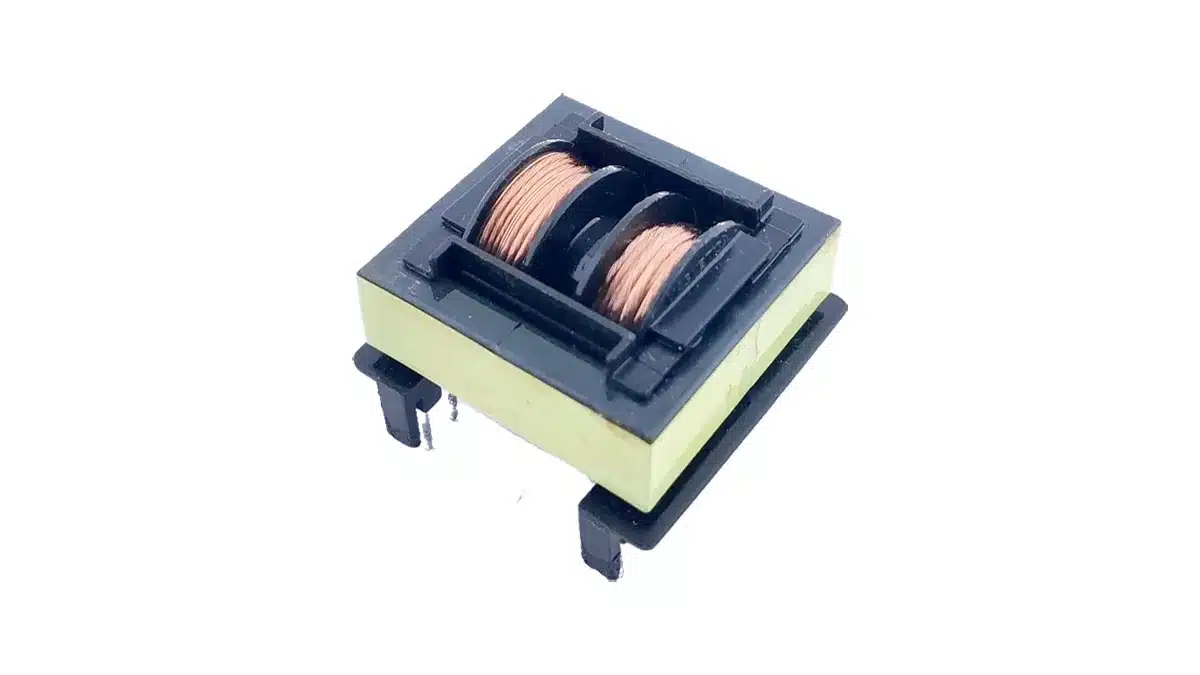
As shown in featured image Figure 1, the transformer primary and secondary windings are separated by a plastic barrier. In low frequency Transformers, that is useful because of its isolation benefits. That is true also for HF 

RelatedPosts

Common Mistakes in Flyback Transformer Specs

Accelerating Full Bridge LLC Resonant Converter Design with Frenetic AI

How to design a 60W Flyback Transformer

Magnetics, but besides the isolation, this winding arrangement approach offers some additional benefits, such as:

  • Isolation between high-low voltage windings.
  • Primary-secondary capacitance is kept to a minimum.
  • Leakage inductance can be adjusted by modifying the barrier thickness between windings.
  • A resonant inductor can be omitted if the leakage inductance is properly chosen.

Let’s focus now on the last two key points just listed, and let’s use the popular half bridge LLC topology for our analysis as shown in Figure 2.:

Figure 2. Half bridge LLC Converter with/without integrated series inductor

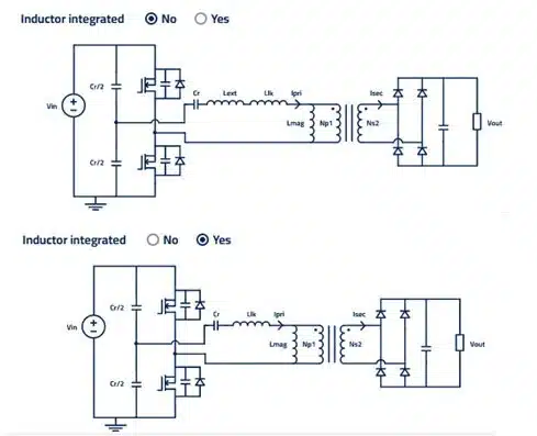
In this screenshot taken from Frenetic Online, you can see the button on the top asking if the series resonant Inductor should be included into the Transformer or not. In theory, we care about the sum of these 2 inductances: if the Llk of the transformer is not enough, we have to add in series Inductor for the sum of two to have the correct value. But, if we modify the Llk to have the final value of series inductance, then we don’t need an external inductor at all!

See where I’m going with this…

The half bridge topology offers some benefits versus the full bridge up to about 2kW, where the high rms currents are causing high losses and the adoption of the full bridge is clearly advantageous.

I tried to create x5 designs with different power levels in order to prove that the 2-chamber approach can be successfully chosen for higher power level applications. But, prior to unfolding these design, I want to focus first on the concerns I had before even starting the simulation in Frenetic Online.

List of concerns…

  • Splitting the available bobbin room in 2 will force me to use multiple layers to fit the windings. That can be very troublesome at high power levels, where skin and proximity losses rule the game and are directly dependent on the layer count. Could I control the winding losses given the constraints?
  • Could I achieve the necessary magnetizing/leakage inductance combo without huge gaps in the core that would create EMI and extra fringing losses on the winding, perhaps?
  • Could I achieve a good power density, so that the designs wouldn’t be large and bulky?
  • Could I achieve 50-50% balance between core-winding losses in all cases, which is the right step achieving optimal temperature rise numbers?

Simulations

Figure 3. Transformer Winding overview (all x5 cases)
Table 1. Transformer simulations and results

The Verdict

Table 1 answers all the concerns and questions I had before! Here all the findings:

  • The power level was raised by 30% in each simulation, from 700W up to 2kW. A ~30% increase is observed in the total Transformer losses in each case, which is easily observed looking at the stable Ploss/Pout ratio, very stable at 0.62%. Only the design at 2kW starts deviating going to 0.67% of losses. That is a good indicator that moving up in power, selecting windings and layout carefully, can keep the winding losses under control. And this answers my first concern mentioned previously.
  • Core-winding losses are designed to be relatively equal at the 400->300V operating condition.
  • I kept the barrier at 3mm, the leakage inductance at 20-30μH and a center leg gap <1.25mm in all five cases. That ensures manufacturability and low noise emissions. The gap effect is insignificant since (as shown in Figure 3) both primary and secondary windings are far from it. The closer to the gap, the higher the fringing losses. In our cases the barrier helps to avoid this.
  • Power density is moving from 7kW/l up to 20kW/l. Actually, below 6-8kW/l usually no forced air cooling is needed to achieve 40-60°C of temperature rise in a magnetic component. You can keep this as a rule of thumb for your designs, no matter the topology. At 700W we have a 7kW/l power density and ~50°C of temperature rise (74-25=49°C) with free convection. In the rest of the designs 1m/s was used.
  • To remember LLC calculations (how to select Lmag, Llk) for half bridges, watch webinar on the topic here.
  • These designs prove that a reasonable power density, thus compact design, can be achieved up to 2kW, which is the useful power range limit of the half bridge LLC topology, without the need for an external inductor!

Maybe you can come up with a Transformer + Inductor design that is denser than suggested, but is it worth the extra component and cost? Is the total power density of the x2 components higher than the one of the 2-chamber transformer?

Related

Source: Frenetic

Recent Posts

Bourns Releases High Current Metal Alloy-based, Multilayer Power Chip Inductors

31.10.2025
3

Common Mode Chokes Selection for RF Circuits in Next-Generation Communication Systems

30.10.2025
7

Capacitor Self-balancing in a Flying-Capacitor Buck Converter

30.10.2025
8

Vishay Releases Space-Grade 150 W 28V Planar Transformers

29.10.2025
14

How to Select Ferrite Bead for Filtering in Buck Boost Converter

23.10.2025
41

Power Inductors Future: Minimal Losses and Compact Designs

30.10.2025
49

Bourns Unveils Automotive 3 Watt Gate Driver Transformer

22.10.2025
9

Percolation Phenomenon: Degradation of Molded Power Inductors in DC/DC Converters

30.10.2025
53

Murata Integrates Component Models into Cadence EDA Tools

21.10.2025
48

Bourns Releases High Inductance Common Mode Choke

16.10.2025
24

Upcoming Events

Nov 4
10:00 - 11:00 PST

Design and Stability Analysis of GaN Power Amplifiers using Advanced Simulation Tools

Nov 4
November 4 @ 12:00 - November 6 @ 14:15 EST

Wirebond Materials, Processes, Reliability and Testing

Nov 6
14:30 - 16:00 CET

Self-healing polymer materials for the next generation of high-temperature power capacitors

View Calendar

Popular Posts

  • Buck Converter Design and Calculation

    0 shares
    Share 0 Tweet 0
  • Boost Converter Design and Calculation

    0 shares
    Share 0 Tweet 0
  • LLC Resonant Converter Design and Calculation

    0 shares
    Share 0 Tweet 0
  • Flyback Converter Design and Calculation

    0 shares
    Share 0 Tweet 0
  • Ripple Current and its Effects on the Performance of Capacitors

    3 shares
    Share 3 Tweet 0
  • MLCC and Ceramic Capacitors

    0 shares
    Share 0 Tweet 0
  • Dual Active Bridge (DAB) Topology

    0 shares
    Share 0 Tweet 0
  • SEPIC Converter Design and Calculation

    0 shares
    Share 0 Tweet 0
  • What is a Dielectric Constant and DF of Plastic Materials?

    4 shares
    Share 4 Tweet 0
  • Flying Capacitors

    0 shares
    Share 0 Tweet 0

Newsletter Subscription


Passive Components Blog

© EPCI - Leading Passive Components Educational and Information Site

  • Home
  • Privacy Policy
  • EPCI Membership & Advertisement
  • About

No Result
View All Result
  • Home
  • Knowledge Blog
  • PCNS

© EPCI - Leading Passive Components Educational and Information Site

This website uses cookies. By continuing to use this website you are giving consent to cookies being used. Visit our Privacy and Cookie Policy.
Go to mobile version