


This article explains basics of What is an Inductor? and What is a Choke? to understand the passive electronic component principles, applications and technologies.
Key Takeaways
- An inductor is a passive electronic component that stores energy in a magnetic field created by current flowing through a coil.
- Inductance measures how effectively the inductor generates magnetic flux for a given current, expressed in henries (H).
- Inductors are essential in power electronics for energy storage, filtering, and impedance matching in circuits.
- A choke is a type of inductor optimized to block AC components while allowing DC to pass, often with a magnetic core to enhance performance.
- Real inductors exhibit parasitic elements, leading to frequency-dependent behavior and self-resonant frequencies.
Inductor Definition
Inductors are passive electrical components that store energy in a magnetic field.
An inductor is formed by a conductive wire wound into a coil, with its ends brought out as terminals. When current flows through the winding, it creates a magnetic field that stores energy around and inside the component. The ratio between the magnetic flux linkage and the current defines the inductance L, expressed in henry (H).
Inductance is usually represented by the symbol “L,” commonly attributed to Lenz and Lenz’s law of electromagnetic induction. In practical circuits, inductors oppose rapid changes in current: they resist current transients, then release stored energy back into the circuit when conditions change.
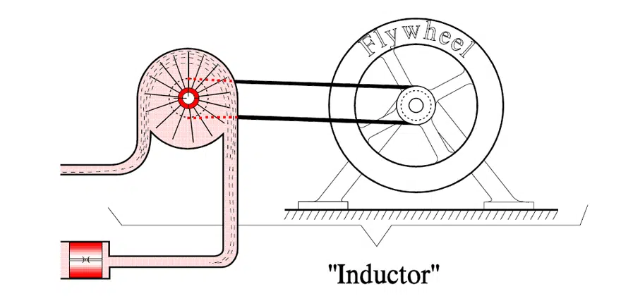
In a hydrodynamic analogy, an inductor behaves like a flywheel in a mechanical system: it requires force to change its rotational speed (current), but once spinning, it tends to maintain motion and smooth out disturbances.
Basic Inductor Structure and Inductance
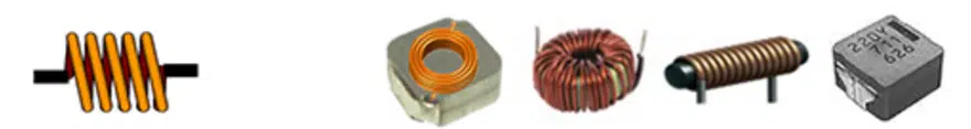
Simple Coil and Core
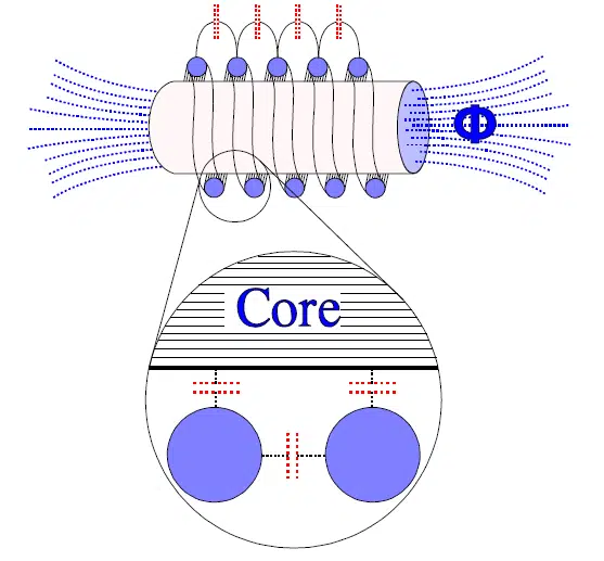
The most basic inductor is just a wire wound into a coil shape. In practice, most inductors include a core made of magnetic material—such as ferrite or laminated steel—to increase inductance and control magnetic flux. The core may form a closed magnetic circuit (for example, toroid, E‑core) to confine the field and reduce leakage.
The inductance of a simple coil can be approximated by:where:
- – inductance (H)
- – Nagaoka coefficient (geometry factor)
- – core permeability (H/m)
- – number of turns
- – coil cross‑sectional area (m²)
- – magnetic path length (m)
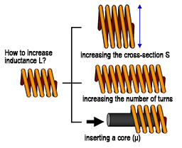
Increasing turns, core permeability, or cross‑section increases inductance, while longer magnetic path length reduces it.
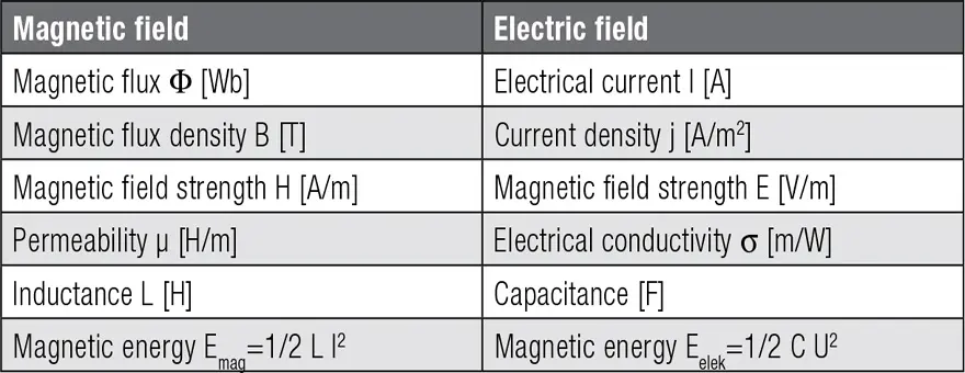
Electric vs Magnetic Field Analogy
Magnetic fields and electric fields have useful analogies: for example, flux vs charge, magnetomotive force vs voltage, and reluctance vs resistance. These analogies help bridge concepts between capacitors (electric fields) and inductors (magnetic fields) when analyzing energy storage and circuit behavior.
Ideal, Series/Parallel and Equivalent Circuit
Series and Parallel Connections
Like resistors or capacitors, inductors can be connected in series or in parallel.
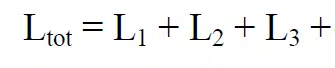
- Series connection: Total inductance is the sum of the individual inductances, assuming no mutual coupling.
- Parallel connection: For loss‑free inductors with the same phase angle, the reciprocal of total inductance is the sum of reciprocals (similar to parallel resistors).
These rules allow designers to realize specific inductance values from standard parts, at the cost of increased parasitics.
Connection in series
Connection in parallel
For loss free coils and coils with the same angle of phase applies

Equivalent Circuit and Parasitics
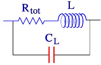
Real inductors deviate from the ideal L element due to parasitic resistance and capacitance. A practical equivalent circuit includes:
- Series resistance – copper losses, core losses reflected as resistance
- Parasitic capacitance – between turns and between winding and core
- Sometimes additional loss elements representing core and dielectric losses
At low frequency, inductive behavior dominates and the inductor looks like L in series with a small resistance. As frequency increases, the parasitic capacitance and losses become significant and eventually define a self‑resonant point.
The stray capacitances between the windings and between windings and core can be summarized to one single total capacitance CL. The winding wire also has resistance and in the magnetic material equivalent loss resistances appear. Taken together the characteristics of the inductor can be described with following equivalent circuit.
Self‑Resonant Frequency
The combination of inductance L and parasitic capacitance creates a parallel resonance at the self‑resonant frequency . At , the inductor’s impedance is maximum; above this frequency, the device behaves increasingly like a capacitor, not an inductor. Manufacturers therefore specify test frequency for inductance measurement at a safe margin below .
Inductive Reactance and AC Behavior
Just as capacitors present capacitive reactance in AC circuits, inductors present inductive reactance . The magnitude of this reactance is given by:where is the frequency in hertz.
Key implications:
- At low frequency, is small, so the inductor behaves more like a short for AC.
- At high frequency, becomes large, so the inductor blocks or attenuates AC signals.
In many applications—such as filters and chokes—the designer exploits this frequency‑dependent impedance to pass DC and low‑frequency components while suppressing high‑frequency noise.
What is a Choke?
A choke is essentially an inductor optimized for blocking or attenuating AC components, especially high‑frequency noise, while allowing DC or low‑frequency current to pass. Chokes usually incorporate a magnetic core to increase inductance and achieve high impedance at the frequencies of interest.
When current flows through a choke, changing magnetic flux induces currents in the core material that try to oppose the change in field, as described by Lenz’s law. Solid cores would suffer excessive eddy currents and heating, so practical cores are made from laminated steel or magnetic powder with insulating binders to limit eddy currents and associated losses.
Inductor Technologies
Inductors can be classified by construction, core material, and intended function.
Common categories include:
- Wirewound inductors: Traditional construction with copper wire wound on a bobbin or core, used from signal lines to power chokes.
- Ferrite core power inductors: High‑permeability ferrite cores for switch‑mode power supplies and energy storage.
- Air‑core inductors: No magnetic core, used where linearity, low loss, and high frequency behavior are critical, at the expense of lower inductance per turn.
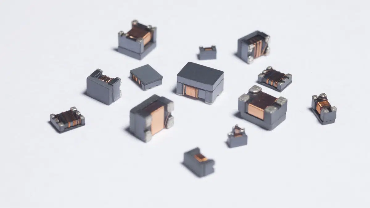
- SMD chip inductors: Miniaturized inductors using ferrite or ceramic cores in surface‑mount packages for RF and power applications.
- Thin‑film and integrated inductors: Implemented on substrates or in silicon for RF ICs and miniaturized designs.
Each technology trades off inductance density, saturation, Q‑factor, frequency range, cost, and mechanical robustness.
Inductor Applications – What is it good for?
Inductors are fundamental elements in power electronics, RF, and general electronics, with several major roles:
- Choking and filtering: Series chokes and common‑mode chokes block or attenuate high‑frequency noise while passing DC and low‑frequency currents, supporting EMC/EMI compliance.
- Energy storage in power converters: Inductors store and transfer energy in buck, boost, flyback, and other DC/DC and AC/DC topologies, shaping current and reducing ripple.
- Resonant circuits and oscillators: Combined with capacitors, inductors form LC “tank” circuits that resonate at specific frequencies for oscillators, filters and impedance matching networks.
- Impedance matching: In RF and high‑frequency circuits, inductors help match source and load impedances to maximize power transfer and minimize reflection.
- EMI reduction: Line filters, differential‑mode and common‑mode chokes suppress conducted and radiated interference in power supplies, motor drives, and communication equipment.
Frequently Asked Questions about Inductors
An inductor is a passive electronic component that stores energy in a magnetic field created by current flowing through a coil, usually wound around a core material.
When current changes through the inductor, the varying magnetic field induces a voltage that opposes the change in current (Lenz’s law), thereby smoothing current transients and storing energy temporarily in the magnetic field.
Inductance is the proportionality between magnetic flux linkage and current; it quantifies how effectively an inductor generates magnetic flux for a given current and is measured in henry (H).
Self‑resonant frequency is the frequency at which the inductor’s inductance and its parasitic capacitance form a resonant circuit, where impedance peaks and above which the component behaves capacitively rather than inductively.
All chokes are inductors, but the term “choke” typically refers to inductors specifically designed to block or filter AC or high‑frequency components while allowing DC or low‑frequency current to pass.
Common constructions include wirewound inductors on ferrite or iron cores, air‑core coils, SMD chip inductors, and integrated or thin‑film inductors for RF and miniaturized designs.
Inductors are used in switch‑mode power supplies, DC/DC converters, EMI filters, RF circuits, resonant converters, motor drive filters, and many other power and signal‑conditioning applications.
How to Understand and Use Inductors
- Identify the inductor type
Determine whether it is a power inductor, RF inductor, common‑mode choke, or integrated inductor, and note core material and mounting style (through‑hole vs SMD).
- Check inductance and current ratings
Ensure the nominal inductance (L) matches your target impedance or ripple requirements, and verify the rated current versus peak and RMS currents in your circuit to avoid saturation and overheating.
- Consider frequency range and self‑resonant frequency
Compare operating frequency with the specified self‑resonant frequency and Q‑factor; choose components whose SRF is comfortably above your highest significant frequency.
- Evaluate DC resistance (DCR) and losses
Confirm that the winding resistance and core losses are acceptable, as these determine efficiency, temperature rise and overall performance in power stages.
- Place the inductor correctly in the circuit and layout
Observe polarity only for devices with marked dot notation when mutual coupling or phasing matters (for example, coupled inductors, transformers), and pay attention to PCB layout for current loops and EMI.
- Use modeling and manufacturer data
Where possible, use manufacturer SPICE or behavioral models that include parasitics to simulate real behavior, especially in high‑frequency or high‑speed power designs.


