


Five MLCC manufacturers and Continental Automotive company as user representative discussed the MLCC Class II DC BIAS & Ageing Capacitance Loss as the Hot Panel Topic during the past 2nd PCNS Passive Components Networking Symposium 10-13th September 2019, Bucharest, Romania. The observations and comments have been summarized as an “Open Letter to AEC-Q200” to follow up the topic in wider automotive industry board.
Introduction
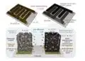
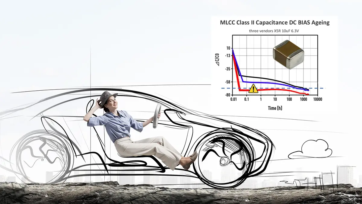
Over the past years, multi-layer ceramic capacitors have undergone significant improvements. The volumetric density has increased several folds. This unfortunately resulted in a big increase in DC and AC bias sensitivity for many parts. In particular, X5R and X7R parts which previously showed only modest bias dependence, exhibit significant capacitance drops. This creates additional challenges for users during the design-in and validation phase.
In consequence, what can be considered as an enabling technology for consumer and wearable applications may pose some risk, if not appropriately designed, in critical safety applications in automotive, medical, aerospace, defence or industrial sectors, that are also in need for continuous miniaturization, but has to make their designs under the worst case scenario.
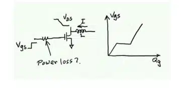
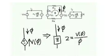
More technical background details and challenges are described in the technical article “High CV MLCC DC/AC Bias Ageing Capacitance Loss Explained” that is submitted as appendix tutorial to this Open Letter.
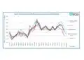
Measurement of Capacitance versus high DC BIAS in mass production present a considerable technical and economical challenge for MLCC manufacturers on the other hand, to be able to 100% guarantee its performance. Manufacturers developed sophisticated software tools to simulate individual part number behaviour at the selected conditions, nevertheless these are so far presented as “typical characteristics” as the best state of the art today.
There is continuous effort to find a common industry approach on handling the MLCC class II DC/AC BIAS ageing issues, especially among the automotive industry. Thus, the next proposed step is to involve AEC-Q200 committee members in wider discussions to recommend a common specification requirement approach between electronic designers / customers and manufacturers across the industry.
More details about the phenomenon has been published in EPCI paper and white paper here.
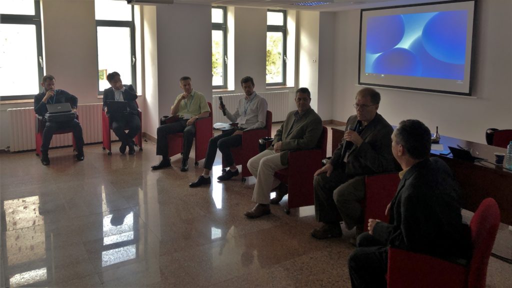
Left to right: Paul Le Nezet Würth Elektronik; Yuki Nagoshi Murata Electronics Europe; Ladislav Vindiš Continental Automotive GmbH; Benjamin Blume Samsung Electro-Mechanics; Wilson Hayworth Kemet Electronics; Ron Demcko AVX Corporation; Tomas Zednicek EPCI
Hot Topic Panel Discussion Record
PANELISTS:
MLCC Manufacturers:
- AVX Corporation: Mr. Ron Demcko
- KEMET Electronics: Mr. Wilson Hayworth
- Murata Electronics Europe: Mr. Yuki Nagoshi
- Samsung Electro-Mechanics: Mr. Benjamin Blume
- Würth Elektronik: Mr. Paul Le Nezet
Automotive User Representative:
- Continental Automotive GmbH: Mr. Ladislav Vindiš
Facilitated by:
- EPCI European Passive Components Institute: Mr. Tomas Zednicek
Introduction
EPCI Tomas Zednicek presented tutorial presentation (as per the „High CV MLCC DC/AC Bias Ageing Capacitance Loss Explained” white paper)
Open Discussion with Panellists
MLCC manufacturers comments and discussions:
- Common declarations:
- Agrees with the tutorial presentation as accurate to reflect the current situation
- There is no intension from anyone to hide any characteristics related to the MLCC class II high CV parts behaviour, in opposite the aim is to disclose and share all data relevant to the behaviour at the operation environment.
- The characteristics are shown in the product datasheets and simulation tools that are under continuous improvement.
- Kemet Electronics : Very important is look at the requirements at the design stage and what effective capacitance is needed. It can be observed for example that C0G MLCC class I stable performance can be very close to the high CV X5R, X7R effective capacitance. In switching power, C0G is also 5-6 times more capable to dissipate the heat and thus use of C0G can be in many cases a better choice instead of class II MLCC.
- Designers must consider capacitance variations of Class II dielectric components whereas Class I dielectrics remain stable over time, voltage, and temperature
- Choose Class I whenever possible
- DC bias Effects become more pronounced when operating at voltages closer to rated voltage and when product size is reduced
- To minimize Class II Bias Voltage Effects, operation should be well below rated voltage.
- Review DC Bias and Temperature Curves and include Aging to calculate the nominal design values so that long term performance is maintained above critical capacitance requirements
- Component miniaturization has created greater DC Bias Effects than the larger product sizes that have been traditionally used
- Include heating effects from switching current and frequency as the part may be performing at elevated temperatures above ambient conditions
- Samsung Electro-Mechanics: We are faced with the requirement for accurate measurement and description of a complex behaviour, with relationships of parameters that are non-linear in nature. Gathering a limited selection of data points over a few hours for a single part number, improves the estimation of capacitance the trend of this specific part. A general application to the automotive MLCC will to be a huge, tedious effort. Guaranteeing the worst-case minimum for all possible applications appears to be impossible.
Continental:
- We
already experienced some issues in critical safety radar system related to the loss
of MLCC capacitance with DC/AC Bias ageing. One manufacturer had inferior
characteristics over the others that resulted in radar out of order stage. There
is still not enough awareness among the design engineers about the issue and
all aspects of different kind of losses that the MLCC class II capacitor can
have. - The
present MLCC characteristics present a challenge for validation phase on
component engineering level as there are many divisions and applications across
our company using the same product at quite different operation conditions. Our
aim is to provide all necessary data about the PN to the designers during the
validation stage that will enable them to make qualified decision on
suitability for their specific application conditions. - The
wish here is to find some consensus how to best specify the characteristics
with MLCC suppliers and its behaviour in the worst-case scenario. - The
designers have many tasks related to the other components and it is difficult
for them to think about all possibilities and scenarios – all active
components, linear and non-linear resistors. The vision is to use accurate
models of PSpice simulation based on high fidelity models, including the worst-case
scenario modelling.
Summary and Final Words
MLCC manufacturers common points:
- There
is currently no immediate solution to guarantee the worst-case Capacitance vs
BIAS data on all MLCC class II capacitors in combination of all operational
conditions, nevertheless there is some evaluation work in progress. - Our
aim is to work on continuous improvement on accuracy and modelling of the
simulation, PSpice and other tools. - AVX:
more data analysis on the issue may be required to propose a universal
solution, the mechanism of capacitance drop is driven by the actual electrical
field across the dielectric. One direction to look from the design point is to evaluate
the specific PN operational electrical field and check if there is some “usable”
link of relationship to the product characteristics, but this needs a lot of data analysis. - Murata:
We are currently analysing and processing our long-term data to introduce new,
more accurate tools to find and predict the minimum capacitance value as the
worst-case scenario.
Proposed Interim Solution:
Continental requirement for new qualifications:
- Going
forward we will require on every single PN MLCC class II capacitors during
qualification and validation from manufacturers:- Capacitance
versus DC-Bias Ageing data measured at room temp., for 24h, at three points:
20,40 and 60% of rated voltage. - Worst
case minimum capacitance value at any operating conditions
- Capacitance
MLCC manufacturers feedback:
- Requirements from Continental is understood as a reasonable and we consider this as applicable at least to a specific PNs dedicated to automotive applications.
- Discussion with other automotive vendors on AEC-Q200 platform is welcome to agree some common industry requirements and implement them into an individual product validation process.
more PCNS symposium technical papers can be viewed at PCNS EPCI e-Symposium library