


Time-dependent capacitance drift of X7R MLCCs under exposure to a constant DC Bias Voltage is one of electronic hardware designers concerns. Vishay publishes its comparative white paper study on this subject.
Vishay White Paper written by Paul Coppens, Eli Bershadsky, John Rogers, and Brian Ward
Until recently, it was assumed that multilayer ceramic capacitor (MLCC) manufacturers’ data stating the typical voltage coefficient of capacitance (VCC) and capacitance loss due to aging (no bias) could be additive, and that further capacitance drift over time will not be significant. However, recent research of the time-dependent capacitance drift of X7R MLCCs under exposure to a constant DC bias voltage – referred to as DC bias aging – has shown there is a time-related capacitance drift that can be much larger than the typical VCC and normal aging effect combined. Further, during PCNS conference an automotive manufacturer reported an issue in critical systems that was related to capacitance loss and DC/AC bias aging [1].
INTRODUCTION
This issue prompted Vishay to conduct a comparative study of DC bias aging on four manufacturers’ 0603 X7R 100 nF, 50 V MLCCs. Vishay and three other manufacturers’ MLCCs were subjected to 40 % and 100 % of their rated voltage for DC bias aging analysis, which spanned over 1000 hours. After periodic intervals of time, the capacitance was measured on all samples with the same DC bias voltage level applied. Results confirmed that prolonged exposure of X7R capacitors to a DC bias voltage leads to a capacitance decrease that is much stronger than the natural drift due to aging.
All competitors’ capacitors show a greater rate of capacitance loss over time compared to Vishay capacitors. Beyond 1000 hours, the Vishay capacitors have the highest remaining capacitance. It was also observed that once bias is removed, Vishay’s capacitance recovers much quicker
than competing parts.
For several decades, multilayer ceramic capacitors (MLCC) have been the preferred choice fo r many surface-mount applications because of their high capacitance, low equivalent series resistance, low cost, and insensitivity to high temperature solder assembly. The stability of their electrical characteristics largely depends on the natureof the dielectric material used. The two commonly used types of ceramic dielectrics are class I and class II. Class I – being a very stable, low loss dielectric material based on paraelectric ceramics – allows only a more limited capacitance range because of its relatively low dielectric constant.
Class I capacitors are excluded from this study because of their natural stability with time, temperature, and voltage. Class II has high dielectric constant materials based on ferro-electric ceramic compositions. High capacitance values can be achieved, but at the cost of higher losses and reduced stability of the electrical characteristics. Several factors will affect the stability of the electrical characteristics in class II capacitors. Among these factors, the most well-known are temperature, DC/AC voltage amplitude, frequency, and the aging of capacitance over time.
Although the effects of DC voltage on capacitance and the gradual decrease of capacitance because of unbiased aging are well known in the industry, little to no attention has been paid to the long term effects of applied DC voltage on capacitance over time. Recently this characteristic, termed DC bias aging, received more attention after application problems were encountered. For a better understanding of the mechanisms that lead to DC bias aging, it is helpful to quickly review the specifics of unbiased aging and the VCC effect.
The VCC effect and unbiased aging are specifically related to the ferroelectric nature of class II MLCCs. A characteristic of ferroelectric dielectrics is the appearance of a spontaneous, permanent polarization. As a result of this spontaneous polarization, the dipoles in a ferroelectric crystal tend to line up, giving rise to ferroelectric domains in which all dipoles have the same direction. [2],[3]. Since the concentration of domains and dipole alignments directly impact the dielectric constant K, any changes or re-orientation of the domains will influence K, and thus capacitance per the following formula:
where:
C = capacitance
n = number of dielectric layers
A = overlap area of each conductive plate (m2)
εo = dielectric permeability of free space (8.854 x 10⁻¹² F/m)
K = dielectric constant
t = thickness separating each dielectric layer (m
MLCC DC BIAS and Ageing Effect Explained
THE VCC DC BIAS EFFECT EXPLAINED
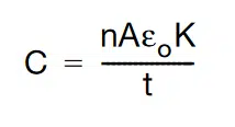
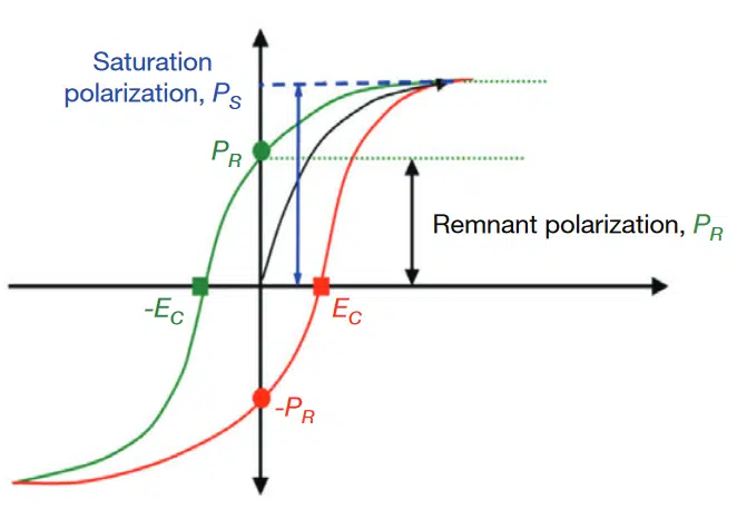
In class II dielectrics, the spontaneous polarization of the ceramic and the associated development of domains is responsible for the initial high capacitance. If the polarization is plotted as a function of the exciting field, as in Fig. 1, a hysteresis loop is obtained. The hysteresis curve shown is typical of barium titanate-based dielectrics. Initially, the polarizability is high, but it gradually levels off as the electrical field is increased. As a result, the capacitance decreases with increasing applied bias voltage, as can be seen in the VCC plot of Fig. 2.
(Hysteresis)
AGING PHENOMENA IN FERROELECTRIC CERAMICS
Above the Curie temperature, barium titanate exhibits a cubic structure. In this state the dielectric is not ferroelectric, and no spontaneous polarization is observed. Upon cooling down below the Curie temperature, the crystal structure changes to tetrahedral. This allows the titanium atom to permanently move off-center in the crystal lattice, giving rise to a permanent polarization. Over time, the domains re-arrange continually, reducing internal strain. This slow rearrangement of domains causes the capacitance to decrease over time. Typically, aging follows a logarithmic law whose mathematical expression is described as:
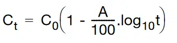
where:
C = capacitance after time t
C0 = initial capacitance
A = aging constant
Usually, aging rates are in the order of 1 % or 2 % per decade. Practically, this means that the capacitance will drop by 1 % or 2 % between 1 hour and 10 hours after de-aging. A similar capacitance drop will occur between 10 hours and 100 hours and between 100 hours and 1000 hours. The aging process can be reversed by heating the dielectric above its Curie point to eliminate the domains. Upon cooling down below the Curie point,the domains are created again, and the aging process restarts from the beginning. This is depicted graphically in Fig. 3.

Normally, the VCC effect and the aging effect are largely independent phenomena. Until recently, it was assumed that the application of a DC bias voltage would reduce the capacitance to a defined level. Upon continuous exposure to a fixed DC bias voltage, only a slow decrease of capacitance due to the aging rate was expected. However, recent reports of the capacitance change over time under the influence of a DC bias voltage indicate that there is a time-related capacitance drift that can be much larger than the normal aging effect. [5][6]. If in an application, the capacitors are exposed to a DC bias voltage for a long time, the knowledge of the VCC and aging effects alone is not sufficient to predict the correct evolution of capacitance over time.
Vishay Comparative Study
THE DC BIAS AGING TEST SETUP AND PROCEDURE

10 0603 X7R 100 nF, 50 V rated capacitor samples from Vishay and three other MLCC manufacturers were mounted on printed circuit boards (PCB). Complete de-aging was performed on all capacitors at 150 °C for a duration of 1 hour prior to testing. These capacitors on PCBs were inserted into a fixture and subjected to a constant DC bias voltage of 40 % and 100 % rated voltage over the entire duration of the test.
After defined periods of time, the PCBs were temporarily removed from their fixtures with parts still holding most of their electrical charge. Capacitance was then measured while applying the same test voltage level and polarity. PCBs were then returned to their fixtures to continue DC bias aging up to 1000 hours.
LONG-TIME EXPOSURE TO 40 % RATED VOLTAGE AT ROOM TEMPERATURE
On one set of samples, all capacitors were subject to 40 % of rated voltage (20 VDC). The capacitors were soaked at this voltage for 10 minutes to allow the initial effect of VCC to settle. Fig. 5 shows the percent capacitance loss over time. This plot references the relative capacitance loss after the immediate effect of bias voltage and VCC. This reference normalizes the initial rate of capacitance loss to 0 % and focuses on each manufacturers’ DC bias aging rate.
Relative Capacitance Change as a Function of Time in 0603 X7R 100 nF, 50 V MLCC With 20 V Bias Application
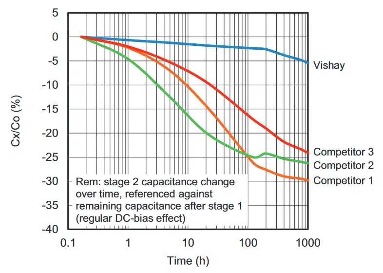
As shown in the plot of Fig. 5, the DC bias aging rates for al l competing parts were far more significant than the 1 % to 3 % per decade usually specified. For example, after 100 hours, comp etitor 2’s part lost an average of 10 % per decade. After 1000 hours, all competing MLCCs lost more than 20 % of their capacitance. While loss rates were far from linear, on average the competitors’ loss rates after three decades (1 hour to 1000 hours) exceeded 7 % per decade with 40% rated DC bias aging.
The Vishay capacitor remained relatively stable throughout the entire test duration, but between 100 hours and 1000 hours the rate increased slightly. Due to its lower capacitance drift, Vishay’s capacitor had the highest remaining capacitance – in total losing an additional 5 % after 1000 hours. DC bias aging for all capacitors appeared to slow down at 1000 hours and was expected to settle to an ultimate value characteristic for the dielectric used.
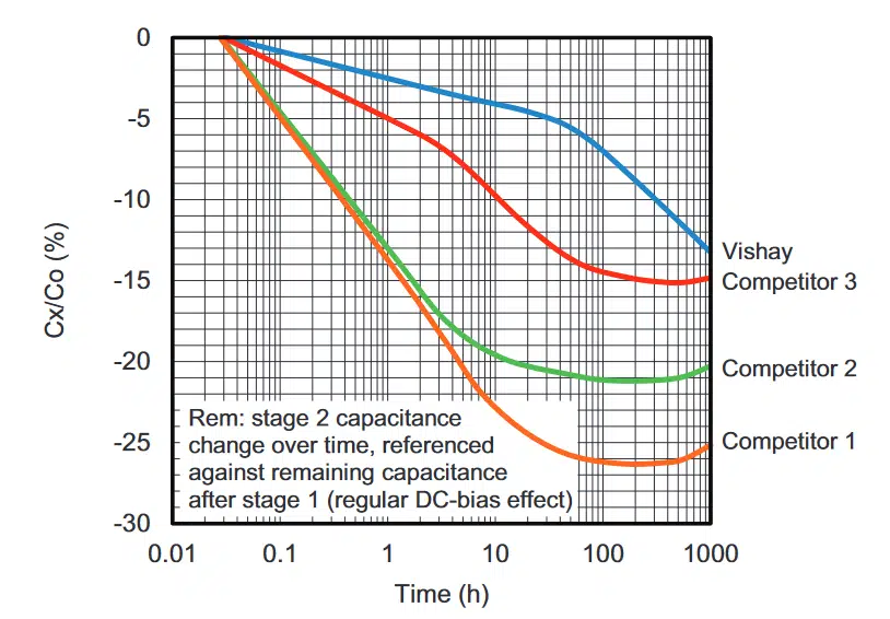
LONG-TIME EXPOSURE TO 100 % RATED VOLTAGE AT ROOM TEMPERATURE
On a second set of samples, the capacitors were subjected to 100 % of rated voltage (50 V DC). The interest here was to see how DC bias aging is affected by a higher field. Fig. 6 shows the capacitance loss over time, again referenced from the capacitance after 50 V bias applied. Comparing Fig. 5’s loss with 40 % bias, and Fig. 6’s loss with 100 % bias, the plot of Fig. 6 shows that capacitance loss proceeds at a faster rate. Competing capacitors initially showed much more capacitance drift under the influence of DC bias than Vishay capacitors, which again remained more stable up to 100 hours. However, this advantage was gradually lost at around 1000 hours of bias exposure.
Relative Capacitance Change Over Time in 0603 X7R 100 nF, 50 V MLCC With 50 V Bias Applied
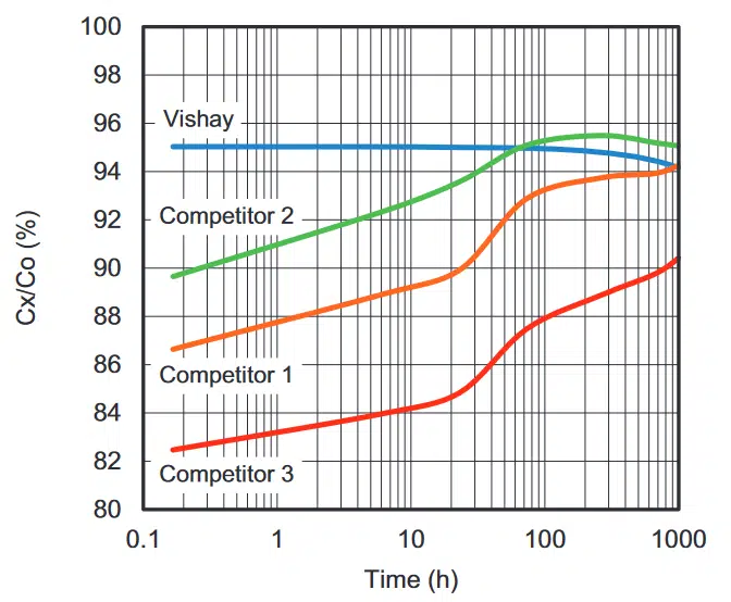
Referring to Fig. 7, after the DC bias voltage was removed, the capacitors slowly recovered from the capacitance drift they experienced from long exposure to 100 % bias voltage. At room temperature, the recovery process for competing parts was slower, taking between 50 hours and 1000 hours to approach 95 %. In comparison, Vishay’s capacitor recovered quite fast to almost 95 % of its initial value. All capacitors tested recovered to 100 % after thermal treatment at 150 °C for one hour (complete de-aging and capacitance drift recovery).
Summary & Conclusions
SUMMARY
LONG-TIME EXPOSURE TO 40 % RATED VOLTAGE AT ROOM TEMPERATURE
Prolonged exposure of X7R capacitors to a DC bias voltage led to a capacitance decrease that was much stronger than the natural drift due to aging. Competing capacitors experienced much more capacitance drift under the influence of DC bias than Vishay’s device, which remained more stable up to 1000 hours. Due to their low capacitance drift under the influence of DC bias voltage, Vishay capacitors have the highest remaining capacitance after longer exposure time. The conclusions are valid for DC bias fields in the order of up to 2.5 V/μm. Since MLCCs are seldom used at 100 % rated voltage, this voltage stress condition is applicable to the majority of the MLCCs in the field.
LONG-TIME EXPOSURE TO 100 % RATED VOLTAGE AT ROOM TEMPERATURE
As in the case of exposure to DC bias at 40 % of rated voltage, prolonged exposure of X7R capacitors to a DC bias voltage leads to a relatively strong capacitance drift. Exposed to the full rated voltage, the capacitance drift proceeds at a much higher rate. Competing capacitors initially showed much more capacitance drift under the influence of DC bias than Vishay’s capacitor, which remained more stable up to 100 hours. Vishay’s adva ntage gradually diminished around 1000 hours of exposure. The conclusions are valid for DC bias fields in the order of 6 V/μm and higher.
RECOVERY RATES
When the DC bias voltage was removed, competing capacitors recovered much more slowly than Vishay’s device, which saw a 95 % capacitance recovery in just a few minutes after bias was removed. Competing capacitors took between 50 hours and 1000 hours or more to reach 95 % recovery. All tested capacitors recovered to 100 % after th ermal treatment at 150 °C for 1 hour.
CONCLUSIONS
Vishay’s introductory testing of the effects of DC bias aging on class II MLCCs supports prior reports. The Vishay capacitor tested proved to be the least affected by DC bias aging, as it had the smallest capacitance drift over time. This study was not an investigation into the physical, chemical, or material reasons for differences in performance between MLCC manufacturers. However, the complete recovery of the capacitance after heating above the Curie temperature seems to indicate that DC bias aging is related to time-dependent changes in the domain structure resulting from prolonged exposure to a bias field.
Also, Vishay MLCCs are produced using noble metal technology. The three competing parts tested were made using base metal technology. These material differences could be a factor explaining the contrast in aging behavior observed. It is now clear that capacitance loss vs. DC bias aging is a critical characteristic that engineers need to know during design evaluation. In response, Vishayis beginning DC bias aging tests on our X7R dielectric systems to provide this data. Vishay’s DC bias aging tests will be conducted for at least 100 hours or greater, with 20 %, 40 %, and 60 % of the rated voltage applied at room temperature.
REFERENCES
[1] Open Letter to AEC-Q200 Committee, High CV MLCC Class II DC/AC Bias Aging Capacitance Loss Issue, Tomas Zednicek Ph.D., pp. 3, September 2019 Issue 1.0
[2] Principles of Electronic Ceramics, chapter 6, L.L. Hench and J.K. West, Wiley Intercedence
[3] Introduction to Ceramics, chapter 19, W.D. Kingery et All, Wiley Interscience
[4] Mechanisms of Aging and Fatigue in Ferroelectrics, Yuri A. Genenko et All, Elsevier Materials Science and Engineering B
[5] Effects of MgO Doping on DC Bias Aging Behavior of Mn-Doped BaTiO3, Dong Woo Hahn et All, Japanese Journal of Applied Physics Vol. 47, No. 7, 2008, pp. 5526 to 5529
[6] Mechanism of Capacitance Aging Under DC Bias Field in X7R-MLCCs, Takaaki Tsurumi et All, J. Electroceram (2008) 21:17-21


