• Latest
  • Trending
  • All
  • Capacitors
  • Resistors
  • Inductors
  • Filters
  • Fuses
  • Non-linear Passives
  • Applications
  • Integrated Passives
  • Oscillators
  • Passive Sensors
  • New Technologies
  • Aerospace & Defence
  • Automotive
  • Industrial
  • Market & Supply Chain
  • Medical
  • RF & Microwave
  • Telecommunication

A Plague Of Parasites

5.6.2017

Examining the Influence of ESR and Ripple Current on Selecting the Suitable Capacitor

21.3.2023

SABIC Validates its 150°C Film Foil to Enable Adoption of Film Capacitors in SIC Power Modules

20.3.2023

Outlook of Passive Electronic Components Market for Oil & Gas Electronics in 2023

20.3.2023

Flying Capacitors Explained

17.3.2023

TDK Introduces Compact High-Current Chokes for Automotive and Industrial Applications

16.3.2023

ECIA NA February 2023 Electronic Components Sales Confirms Growth Trend

16.3.2023
  • Home
  • Privacy Policy
  • EPCI Membership & Advertisement
  • About
No Result
View All Result
NEWSLETTER
Passive Components Blog
  • Home
  • NewsFilter
    • All
    • Aerospace & Defence
    • Antenna
    • Applications
    • Automotive
    • Capacitors
    • Circuit Protection Devices
    • Filters
    • Fuses
    • Inductors
    • Industrial
    • Integrated Passives
    • Market & Supply Chain
    • Medical
    • New Materials & Supply
    • New Technologies
    • Non-linear Passives
    • Oscillators
    • Passive Sensors
    • Resistors
    • RF & Microwave
    • Telecommunication

    Examining the Influence of ESR and Ripple Current on Selecting the Suitable Capacitor

    SABIC Validates its 150°C Film Foil to Enable Adoption of Film Capacitors in SIC Power Modules

    Outlook of Passive Electronic Components Market for Oil & Gas Electronics in 2023

    Flying Capacitors Explained

    TDK Introduces Compact High-Current Chokes for Automotive and Industrial Applications

    ECIA NA February 2023 Electronic Components Sales Confirms Growth Trend

    Investigating Modeling Techniques of Class II Ceramic Capacitors Losses for High Voltage and Current Applications

    TDK Extends Range of Industrial Single Pair Ethernet (SPE) Inductors

    Premo Unveils New series of 11kW 3-Phase On-Board Charger Transformers

    Trending Tags

    • Ripple Current
    • RF
    • Leakage Current
    • Tantalum vs Ceramic
    • Snubber
    • Low ESR
    • Feedthrough
    • Derating
    • Dielectric Constant
    • New Products
    • Market Reports
  • VideoFilter
    • All
    • Antenna videos
    • Capacitor videos
    • Filter videos
    • Fuse videos
    • Inductor videos
    • Non-linear passives videos
    • Oscillator videos
    • Passive sensors videos
    • Resistor videos
    • Sensors

    Investigating Modeling Techniques of Class II Ceramic Capacitors Losses for High Voltage and Current Applications

    Understanding Basics of Current Sense Resistors

    What Decoupling Capacitor Value To Use And Where To Place Them

    How to Measure Rated Current on Power Inductors

    LTspice Simulation of a Spark-Gap Circuit Protection Surge Arrester

    Approximate Inductor Design Using Two Alternative Cores

    1kW Phase Shift Full Bridge Converter Design and Simulation

    Multiphase Buck Trans-Inductor Voltage Regulator (TLVR) Explained

    Smart Power Distribution Unit Architecture and Inductor Losses

    Trending Tags

    • Capacitors explained
    • Inductors explained
    • Resistors explained
    • Filters explained
    • Application Video Guidelines
    • EMC
    • New Products
    • Ripple Current
    • Simulation
    • Tantalum vs Ceramic
  • Knowledge Blog
  • Suppliers
    • Preferred Suppliers
    • Who is Who
  • Events
No Result
View All Result
Passive Components Blog
No Result
View All Result

A Plague Of Parasites

5.6.2017
Reading Time: 7 mins read
0 0
0
SHARES
804
VIEWS

Source: ECN article

06/02/2017 by Paul Pickering, Technical Contributor

RelatedPosts

Examining the Influence of ESR and Ripple Current on Selecting the Suitable Capacitor

SABIC Validates its 150°C Film Foil to Enable Adoption of Film Capacitors in SIC Power Modules

Outlook of Passive Electronic Components Market for Oil & Gas Electronics in 2023

Any discussion of plagues and parasites brings to mind thoughts of locusts, frogs, and biting insects. Thankfully, such events are rare in 2017, but if you work with high-speed digital and analog circuitry, there’s one sure way to risk a disaster of Biblical proportions: forgetting that the printed circuit board (PCB) is much more than a benign way to hook up your components.

As we all learned in school and (if you’re like me) promptly forgot, when frequencies increase, a PCB becomes anything but harmless. In fact, it’s then a component in its own right: a complex passive network of parasitic resistors, inductors, and capacitors that can wreak havoc with marginal designs.

The PCB As A Passive Network

PCB parasitics include inductors formed by package leads and long traces; pad-to-ground, pad-to-power-plane, and pad-to-trace capacitors; interactions with vias, and more.

Figure 1: The equivalent circuit per unit length of a PCB trace contains resistive, inductive, and capacitive elements. (Source: electronics.stackexchange.com)

Models are a good way to simulate the electrical contributions of PCB parasitics. Figure 1 shows the basic block of the distributed element model (transmission line model) of a PCB trace: R, L, and C are exactly what you’d expect; G is the conductance of the PCB dielectric.

Quantifying PCB Parasitics

How can we get an idea on the magnitude of these PCB parasitics? Let’s start with trace resistance.

The standard PCB uses 1-oz copper traces, which have a thickness equal to one ounce of copper evenly spread over a one square foot area, or 1.37 thousandths of an inch (mils). The 1-oz copper has a resistivity of ~ 0.5 mΩ per square, which equates to 5 mΩ for a 10-mil trace per 100 mil of length.

Since most low-power designs do not carry more than a few milliamps of current, the effect on trace resistance is often negligible. For high-current paths, though, even a few milliohms can cause voltage drops and excessive temperatures, calling for wider traces.

PCB capacitance and inductance pose greater problems because they can couple RF voltages and currents into nearby traces and reduce the effectiveness of decoupling capacitors and EMC filters.

The dimensions of a trace or via, plus the relative permittivity, εr, of the PCB material, determine its inductance and capacitance. FR-4 glass-reinforced epoxy, the most common PCB material, has an εr range from 4.0 to 5.0: 4.5 is often used as a typical value.

Figure 2: The formulas for calculating trace inductance and capacitance. (Source: Texas Instruments)

The formulas for PCB inductance and capacitance are complicated: the ones given in Figure 2 and 3 are approximations. A 0.8 mm (0.031”) trace on a 0.8 mm (0.031”) thick FR-4 PCB, for example, has about 4 nH inductance and 0.8 pF capacitance per cm, or ˜ 10 nH and 2.0 pF per inch.

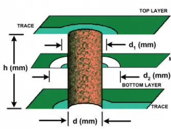
Figure 3: The equivalent formulas for vias. (Source: Texas Instruments)

A different set of approximations applies to PCB vias—connections that route signals between different PCB layers.

Applying the equations in Figure 3, a 0.4 mm (0.0157”) via through a 1.6 mm (0.063”) PCB has ˜ 1.2 nH inductance; even the clearance hole can contribute some parasitic capacitance.

Since the length of a via is typically very small relative to the rest of the trace, its contribution is often ignored. This can cause issues, though with very high frequency (>100MHz) signals, or in situations where the high-frequency harmonics contain significant energy.

To save you ploughing through the math, help is available online. The Vehicular Electronics Laboratory at Clemson University, for example, offers online calculators for several transmission methods including surface microstrips, embedded microstrips, and striplines.

Some Effects Of PCB Parasitics

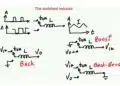
PCB parasitics cause problems in a variety of areas. In a switching power supply—a synchronous buck converter, for example—parasitic inductance can slow down the turn-on and turn-off time of the power FET and increase switching losses.

Figure 4: In a synchronous buck converter, the internal and external inductances in the source path of the HS FET combine to form the common-source inductance (LCSI). (Source: EEWordsmith)

As Figure 4 illustrates, the inductances of both the PCB trace and the FET’s internal bond wires contribute to the total inductance between the HS FET source and the gate driver return path.

Both the (high) drain-source current and (low) gate-charging current flow through the common-source inductance. A change in IDS will induce an opposing voltage VCSI in LCSI, and modify the gate-source voltage VGS seen by the power MOSFET. The effect is an increase in FET turn-on and turn-off times, resulting in increased switching losses.

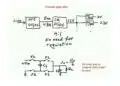
Parasitics can also change the performance of high-speed analog designs. Figure 5 shows a typical op amp circuit as it appears on the schematic, and real-world circuit on a PCB; every pad adds a parasitic capacitor, and every trace adds a parasitic inductor. Just for fun, resistors, capacitors, and inductors are far from ideal and each one adds its own set of parasitics to the mix.

As little as one pf of unwanted parasitic capacitance at the inverting input of an op amp can cause an additional 2 dB of gain at high frequencies; a few nH of added inductance from a two-inch trace can result in a low-level oscillation.

Figure 5: (a) A typical op amp design schematic, and (b) the design with parasitics included. (Source: Analog Devices)

Digital designs aren’t immune, of course. The latest USB 3.1 SuperSpeed+ specification allows for data rates of 10 Gbps; HDMI 2.1 has four data lanes, each running at 12 Gbps.

At these speeds, it’s critical to maintain impedance matching throughout the signal path. Any mismatch caused by PCB parasitic capacitance will cause reflections on the line, increase jitter, and compromise signal quality.

General Guidelines For Reducing The Effects Of Parasitics

Paying close attention to PCB layout can go a long way in reducing parasitics. Manufacturers of high-speed analog and digital circuits offer numerous application notes, tutorials, and seminar material on PCB layout best practices: the information from Texas Instruments and Analog Devices is particularly instructive. For digital circuitry, Howard Johnson and Martin Graham have written a well-regarded book on high-speed digital design, appropriately subtitled A Handbook of Black Magic that covers many of these topics.

IC suppliers can help reduce the effects of PCB parasitics, too.

In the digital arena, devices placed in the high-speed data path often employ “flow-through” packaging that helps keep the trace lengths equal between the positive and negative lines of the differential data lanes to avoid impedance mismatch.

In power ICs, manufacturers are working to reduce the effects of internal parasitics from such items as bond wires and pins. Texas Instruments, for example, offers its PowerStack technology that places two NexFET power transistors directly on top of each other in a three-dimensional package; this arrangement virtually eliminates resistance and parasitic inductance between the FETs. In a synchronous buck converter, that translates to lower common source inductance, resulting in lower switching losses and higher efficiency.

Conclusion

There’s a popular quote, usually (though erroneously) attributed to Mark Twain: “It ain’t what you don’t know that gets you into trouble. It’s what you know for sure that just ain’t so.”

Paying attention to the effects of the PCB on your high-speed design will not only keep you out of the second category, it might also avoid a plague. In this case, of late nights, lost weekends, and angry bosses.

Best of luck with the frogs and the rest. Although I do like a plate of cuisses de grenouille now and then. Locusts, not so much.

Related Posts

Applications

More Compact Multiple Output Power Supply with Just One Inductor

18.1.2023
36
Inductors

Planar vs Traditional Transformers in Flyback Converters

8.11.2022
275
Applications

Digi-Key Electronics Announces 2022 Back2School Prize Draw

26.9.2022
16

Upcoming Events

Mar 19
March 19 - March 23

APEC 2023

Mar 22
14:00 - 15:00 CET

Parasitic Components in Power Converters – Fundamentals and Measurements Rohde & Schwarz Webinar

Apr 3
April 3 @ 12:00 - April 4 @ 14:00 CEST

Microelectronic Packaging Failure Modes and Analysis

View Calendar

Popular Posts

  • What is a Dielectric Constant of Plastic Materials ?

    4 shares
    Share 4 Tweet 0
  • Ripple Current and its Effects on the Performance of Capacitors

    3 shares
    Share 3 Tweet 0
  • Understanding High-Precision Resistor Temperature Coefficient of Resistance

    0 shares
    Share 0 Tweet 0
  • Capacitor Selection for Coupling and Decoupling Applications

    28 shares
    Share 28 Tweet 0
  • Leakage Current Characteristics of Capacitors

    0 shares
    Share 0 Tweet 0
  • How to Choose the Right Inductor for DC-DC Buck Applications

    0 shares
    Share 0 Tweet 0
  • Dielectric Constant and its Effects on the Properties of a Capacitor

    7 shares
    Share 7 Tweet 0
  • MLCC and Ceramic Capacitors

    0 shares
    Share 0 Tweet 0

Newsletter Subscription


PCNS Call for Papers !

Archive

2022
2021
2020
2019
2018
2017

Symposium

Passive Components Networking Symposium

Passives e-Learning

Knowledge Blog

  • Home
  • Privacy Policy
  • EPCI Membership & Advertisement
  • About

© EPCI - Premium Passive Components Educational and Information Site

No Result
View All Result
  • Home
  • News
  • Video
  • Knowledge Blog
  • Preferred Suppliers
  • Events

© EPCI - Premium Passive Components Educational and Information Site

Welcome Back!

Login to your account below

Forgotten Password?

Retrieve your password

Please enter your username or email address to reset your password.

Log In
This website uses cookies. By continuing to use this website you are giving consent to cookies being used. Visit our Privacy and Cookie Policy.