Passive Components Blog
No Result
View All Result
  • Home
  • News
    • All
    • Aerospace & Defence
    • Antenna
    • Applications
    • Automotive
    • Capacitors
    • Circuit Protection Devices
    • electro-mechanical news
    • Filters
    • Fuses
    • Inductors
    • Industrial
    • Integrated Passives
    • inter-connect news
    • Market & Supply Chain
    • Market Insights
    • Medical
    • Modelling and Simulation
    • New Materials & Supply
    • New Technologies
    • Non-linear Passives
    • Oscillators
    • Passive Sensors News
    • Resistors
    • RF & Microwave
    • Telecommunication
    • Weekly Digest
    onsemi solid-state transformer concept for 800 V HVDC AI data center power conversion with SiC modules, DC-link capacitors and high-frequency magnetics

    Solid-State Transformers for 800 V AI Data Centers: Passive Component Design Considerations

    Littelfuse TX00AT314AMA omnipolar TMR magnetic switch sensor in a leaded TO-92-3 through-hole package

    Littelfuse Expands Omnipolar TMR Switch with Leaded TO-92 Package Option

    SCHURTER THT DIP Switches Support Hardware-Level Configuration

    TDK CN series 10 µF 100 V X7R soft-termination multilayer ceramic capacitor in 3225 EIA 1210 package

    TDK Releases 100 V Soft-Termination X7R MLCCs 10 uF in 3225 Package

    Compact inductive rotary position encoder sensor near a motor shaft, representing the Vishay RAIK045I MP encoder category

    Vishay Introduces 16-Bit Inductive Encoder for Motor-Adjacent Position Sensing

    Hirose FH51 automotive FPC/FFC connector with low-profile receptacle construction and top-and-bottom contact arrangement

    Hirose Automotive FPC/FFC Connector Adds One-Action Mating up to 125°C

    Overview of fabricated ferroelectric capacitors improving hyperdimensional computing task learning accuracy. a The experimental work reported in this study comprises ferroelectric capacitor (FeCAP) device fabrication, structural and electrical characterization, analog state identification and their reliability study. b The computational part of the work explores the benefits of using characteristics from the fabricated devices in a hyperdimensional computing scheme; source: authors

    High-Precision Hyperdimensional Computing with Multi-Level Ferroelectric HZO Capacitors

    Coilcraft Introduces Automotive Common Mode Chokes Target CISPR 25 Class 5 EMC Compliance

    Murata Expands Automotive Metal Power Inductor Range

    Trending Tags

    • Ripple Current
    • RF
    • Leakage Current
    • Tantalum vs Ceramic
    • Snubber
    • Low ESR
    • Feedthrough
    • Derating
    • Dielectric Constant
    • New Products
    • Market Reports
  • Knowledge Blog
  • Dossiers
    • AI Hardware Dossier
    • Automotive Dossier
    • Industrial Robotics Dossier
    • Power Converter Dossier
    • Capacitor Dossier
    • Resistor Dossier
    • Inductor Dossier
    • Circuit Protection Dossier
  • Suppliers
    • Who is Who
  • PCNS
    • PCNS 2025
    • PCNS 2023
    • PCNS 2021
    • PCNS 2019
    • PCNS 2017
  • Events
  • Home
  • News
    • All
    • Aerospace & Defence
    • Antenna
    • Applications
    • Automotive
    • Capacitors
    • Circuit Protection Devices
    • electro-mechanical news
    • Filters
    • Fuses
    • Inductors
    • Industrial
    • Integrated Passives
    • inter-connect news
    • Market & Supply Chain
    • Market Insights
    • Medical
    • Modelling and Simulation
    • New Materials & Supply
    • New Technologies
    • Non-linear Passives
    • Oscillators
    • Passive Sensors News
    • Resistors
    • RF & Microwave
    • Telecommunication
    • Weekly Digest
    onsemi solid-state transformer concept for 800 V HVDC AI data center power conversion with SiC modules, DC-link capacitors and high-frequency magnetics

    Solid-State Transformers for 800 V AI Data Centers: Passive Component Design Considerations

    Littelfuse TX00AT314AMA omnipolar TMR magnetic switch sensor in a leaded TO-92-3 through-hole package

    Littelfuse Expands Omnipolar TMR Switch with Leaded TO-92 Package Option

    SCHURTER THT DIP Switches Support Hardware-Level Configuration

    TDK CN series 10 µF 100 V X7R soft-termination multilayer ceramic capacitor in 3225 EIA 1210 package

    TDK Releases 100 V Soft-Termination X7R MLCCs 10 uF in 3225 Package

    Compact inductive rotary position encoder sensor near a motor shaft, representing the Vishay RAIK045I MP encoder category

    Vishay Introduces 16-Bit Inductive Encoder for Motor-Adjacent Position Sensing

    Hirose FH51 automotive FPC/FFC connector with low-profile receptacle construction and top-and-bottom contact arrangement

    Hirose Automotive FPC/FFC Connector Adds One-Action Mating up to 125°C

    Overview of fabricated ferroelectric capacitors improving hyperdimensional computing task learning accuracy. a The experimental work reported in this study comprises ferroelectric capacitor (FeCAP) device fabrication, structural and electrical characterization, analog state identification and their reliability study. b The computational part of the work explores the benefits of using characteristics from the fabricated devices in a hyperdimensional computing scheme; source: authors

    High-Precision Hyperdimensional Computing with Multi-Level Ferroelectric HZO Capacitors

    Coilcraft Introduces Automotive Common Mode Chokes Target CISPR 25 Class 5 EMC Compliance

    Murata Expands Automotive Metal Power Inductor Range

    Trending Tags

    • Ripple Current
    • RF
    • Leakage Current
    • Tantalum vs Ceramic
    • Snubber
    • Low ESR
    • Feedthrough
    • Derating
    • Dielectric Constant
    • New Products
    • Market Reports
  • Knowledge Blog
  • Dossiers
    • AI Hardware Dossier
    • Automotive Dossier
    • Industrial Robotics Dossier
    • Power Converter Dossier
    • Capacitor Dossier
    • Resistor Dossier
    • Inductor Dossier
    • Circuit Protection Dossier
  • Suppliers
    • Who is Who
  • PCNS
    • PCNS 2025
    • PCNS 2023
    • PCNS 2021
    • PCNS 2019
    • PCNS 2017
  • Events
No Result
View All Result
Passive Components Blog
No Result
View All Result

Addressing EMI Challenges in EVs with GaN-based OBCs

14.9.2022
Reading Time: 8 mins read
A A

Brent McDonald, TI system engineer of power supply design services discusses EMI conducted emissions challenges in electric vehicles with GaN-based OBCs in his article published by Analogue Design Journal.

Introduction

The onboard charger (OBC) is an essential element in any electric vehicle. In order to reduce the size and weight of the vehicle, wide band-gap devices
such as gallium nitride (GaN) are a popular choice for implementing power conversion. GaN switches have low output capacitance (COSS) that enables them to switch faster and more efficiently than traditional silicon metal oxide semiconductor field-effect transistors (MOSFETs), enabling a dramatic reduction in the volume of the OBC.

RelatedPosts

Solid-State Transformers for 800 V AI Data Centers: Passive Component Design Considerations

Littelfuse Expands Omnipolar TMR Switch with Leaded TO-92 Package Option

SCHURTER THT DIP Switches Support Hardware-Level Configuration

The faster switching speed does raise concerns about the associated impact to the electromagnetic interference (EMI) signature, however. This article reviews the Comité International Spécial des Perturbations Radioélectriques (CISPR) 32 EMI requirements for an OBC and discuss measurement best
practices for reliable data, the impact of GaN on the EMI spectrum, and ideas to help resolve observed conducted emissions problems.

System overview

Figure 1 is a schematic for an OBC. The power factor correction (PFC) comprises two phases operating 180° out of phase at a fixed frequency of 120 kHz
each. The capacitor-inductor-inductor-inductor-capacitor (CLLLC) is operating with a variable frequency between 250 kHz and 800 kHz. Under full power operation (6.6 kW), the CLLLC operates with a nominal frequency of about 500 kHz. The system is liquid-cooled with an aluminum cold plate, represented at the bottom of Figure 1. This cold plate is of particular importance to the EMI discussion because it connects to earth ground; any parasitic capacitance to the cold plate therefore has the potential to generate common-mode emissions.

Figure 1 shows the filter’s structure, along with the relevant connections to the AC source and the OBC. The filter is a two-stage filter with differential-mode
inductance
coming from the leakage inductance in the common-mode chokes.
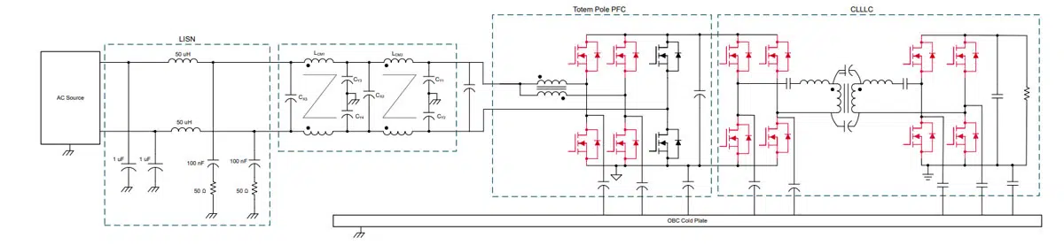
Figure 1. OBC On Board Charger Schematic; source: Texas Instruments
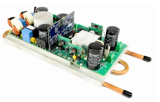
Figure 2. OBC hardware with liquid cooled cold plate. Source: Texas Instruments

Figure 2 shows the physical system with the cold plate attached.

EMI filter design

Generally, EMI includes differential- and common-mode noise. In an OBC system, the input current of the PFC is the main generator of differential-mode noise, while common-mode noise may come from both the PFC and CLLLC. Figure 1 shows parasitic capacitances between the switching nodes to the cold plate, between the primary and secondary grounds to the cold plate, and between the primary and secondary windings of the CLLLC transformer. These parasitic capacitances can generate or affect the common-noise noise current levels in the system [1].

With estimated parasitic capacitances, simulations show that in the worst case, the bare differential-mode noise only with the 2.2-µF input capacitor, CX1, is about 110dBµV. Likewise, the bare common-mode noise without a common-mode filter is about 115 dBµV at about 350 kHz. The design of a two-stage filter, as shown in Figure 1, attenuates the EMI noise below the CISPR 32 standard [2]. The common-mode impedance of LCM1 and LCM2 in Figure 1 at 350 kHz is about 3 kΩ, and their leakage inductances are about 6.4 µH, which are used for differential-mode noise attenuation.

In Figure 1, CX1 and CX2 are 2.2-µF film capacitors for differential-mode noise attenuation, and CY1, CY2, CY3 and CY4 are 4.7-nF ceramic capacitors for common mode noise attenuation. Ideally, with the designed filter, both the bare common-mode noise and the bare differential-mode noise should be attenuated by more than 65 dBµV, and the EMI noise should meet the CISPR 32 standard. There are still some practical challenges at high frequencies and in practical tests, however.

Measurement setup

Measurement setup is crucial in understanding the challenges associated with EMI. Figure 3 shows the essential elements to consider. The OBC requires a 12-V power source in order to power the control and bias circuitry. This bias is not generated in the unit under test, and therefore some kind of auxiliary power supply is required for operation.

Before selecting a power supply, it is important to recognize that any bench-mounted test equipment will have its own internal Y-capacitors. These capacitors
create a path through which common-mode currents inside the OBC can flow. But since these capacitors are not part of the system under test, their influence is an error in any measured EMI. Using a power supply (in this case, a 12-V battery) that is well isolated from earth ground helps avoid this problem.
The load for the OBC has the same potential issue, necessitating the use of a resistive load bank. In addition, although a PC was used to configure the OBC for operation, it was removed before running the EMI scan; thus it is not shown in the measurement setup.
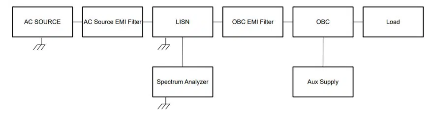
Figure 3. Block diagram of OBC EMI measurement test setup; Source: Texas Instruments

Results

Several challenges occurred during the testing phase. Initial tests attempted to characterize the EMI with an electronic load, auxiliary power supply and a PC,
all connected to the OBC during the EMI scan. This created problems from the multiple ground return paths through the test equipment and PC. All of these items have internal Y-capacitors that create the opportunity for common-mode noise to flow. Ultimately, removing the PC during the test, using a battery for the auxiliary power supply, and changing to a resistive load eliminated these paths.

After addressing the grounding problems in the measurement setup, there was still a need to improve the spectrum significantly. Notice that Figure 3 shows a filter in series with the AC source. The only EMI that I want to measure is what the OBC generates. Any EMI generated by the AC source is a problem that has nothing to do with the OBC. After determining that the AC source was injecting a nontrivial amount of noise into the measured spectrum, adding a filter in series with the AC source prevented any source-generated conducted emissions from corrupting the measured EMI signature of the OBC.

Early on during system development, there was an additional safety X-capacitor in the EMI filter not shown in Figure 1. This X-capacitor is denoted as CX0 in Figure 4. This capacitor was part of a 240-kHz resonance created by CX0, the filter to OBC parasitic interconnect inductances (LP1 and LP2), and CX1. As noted earlier, each phase of the PFC runs at 120 kHz and 180° out of phase from each other. This means that 240 kHz is the fundamental of the current created by the PFC. Since the resonance occurred at this frequency, a significant increase in amplitude of the 240 kHz component of the spectrum occurred. Removing CX0 eliminated this resonance.
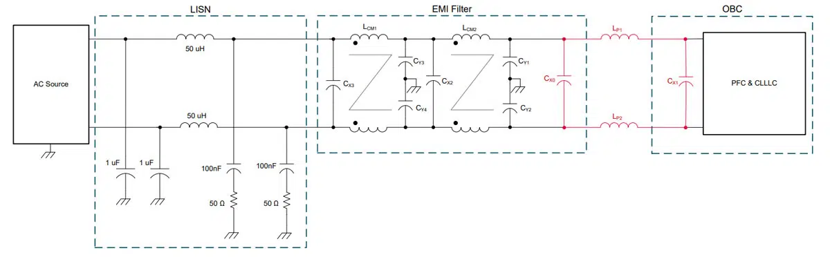
Figure 4. OBC EMI filter with parasitic resonance highlighted; Source: Texas Instruments

The next most significant issue was noise bypassing the EMI filter, which was addressed by using a shield around the EMI filter as well as shielded cables for the interconnect. When shielding the EMI filter, the entire EMI filter was removed other than CX1 from the main board. The EMI filter was placed inside a shielded enclosure. Eventually, a set of 4.7 nF safety Y-capacitors (CY5 and CY6) were placed back on the main board at a location very close to where the chassis ground of the main board connected to the cold plate. Adding these capacitors significantly reduced the EMI spectrum above 5MHz. Figure 5 shows the final filter with the additional Y-capacitors.
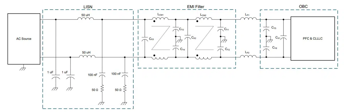
Figure 5. Final OBC EMI filter with CX0 removed; Source: Texas Instruments

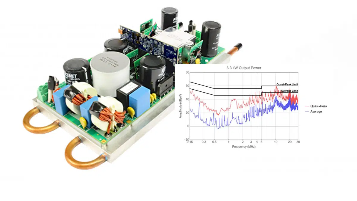
Figure 6 shows the final EMI performance. At this point, all that remains is a small resonance near 10 MHz. To address this resonance, you can improve the high-frequency characteristics of the common-mode inductor in the second stage of the filter, improve the printed circuit board layout, or add another stage with ferrite beads or small common-mode chokes for high-frequency noise filtering.
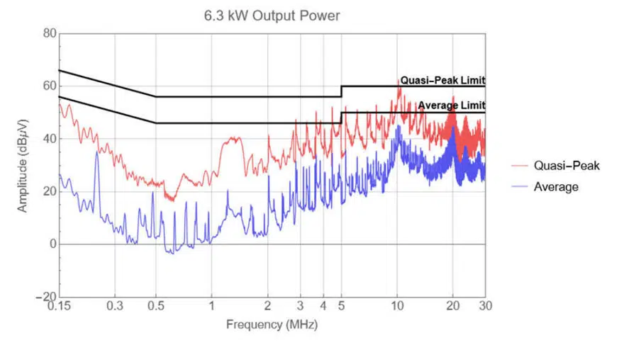
Figure 6. Full power EMI filter scan; Source: Texas Instruments

Conclusion

EMI is very dependent on both the electrical characteristics and the physical construction of the system. These factors make it difficult to list a simple
formula for successfully reducing EMI. It is possible, however, to highlight a few important points after debugging the issues in this example:

  • Grounding is the most important aspect of the filter design and test. Understanding all of the return paths in your system is essential for both proper assessment of EMI and any reductions in EMI levels.
  • What is on the schematic is not the whole story. On paper, your filter may have all of the attenuation you will ever need. In reality, however, the filter is going to have unaccounted-for parasitic capacitance and mutual inductance coupling paths. These paths can make managing EMI very difficult, especially at high frequencies but also at low frequencies. Remember that small signal behavior is not always the same as large signal behavior. How a filter behaves with small current amplitudes is not necessarily the same as how that same filter will behave when heavily loaded.
  • GaN can increase the power density of the power supply without adversely impacting the EMI spectrum. While the power-density improvements that GaN enables were not discussed in this article, you can see that it was possible to deal with any associated impacts from the faster slew rate or switching frequency by using conventional EMI mitigation strategies. In fact, nothing in the data suggests that the EMI issues for this design were any worse than for a silicon-based design. This is perhaps the most significant result, because mitigating concerns about this factor enhances the attractiveness of GaN.

The GaN-Based, 6.6-kW Bidirectional Onboard Charger Reference Design includes the schematic, layout and test results enabled by TI’s GaN FETs.

References

  1. Yongbin Chu, Ashish Kumar, and Yogesh Ramadass. Common-Mode EMI Cancellation in Full-Bridge Based Isolated DC-DC Converters. Published in 2021 IEEE Applied Power Electronics Conference and Exposition (APEC), June 14-17, 2021, pp. 284-291. doi: 10.1109/APEC42165.2021.9487124.
  2. “Electromagnetic Compatibility of Multimedia Equipment – Emission Requirements.” CISPR 32: CISPR: Geneva, Switzerland, October 2019


Related

Source: TI Analogue Design Journal

Recent Posts

onsemi solid-state transformer concept for 800 V HVDC AI data center power conversion with SiC modules, DC-link capacitors and high-frequency magnetics

Solid-State Transformers for 800 V AI Data Centers: Passive Component Design Considerations

9.9.2026
24
TDK CN series 10 µF 100 V X7R soft-termination multilayer ceramic capacitor in 3225 EIA 1210 package

TDK Releases 100 V Soft-Termination X7R MLCCs 10 uF in 3225 Package

9.9.2026
6
Overview of fabricated ferroelectric capacitors improving hyperdimensional computing task learning accuracy. a The experimental work reported in this study comprises ferroelectric capacitor (FeCAP) device fabrication, structural and electrical characterization, analog state identification and their reliability study. b The computational part of the work explores the benefits of using characteristics from the fabricated devices in a hyperdimensional computing scheme; source: authors

High-Precision Hyperdimensional Computing with Multi-Level Ferroelectric HZO Capacitors

7.9.2026
19

August 2026 Interconnect, Passives and Electromechanical Components Market Insights

4.9.2026
35

Knowles Cornell Dubilier 105C Flatpack Aluminum Electrolytic Capacitors Target Low-Profile High-Density Power Designs

4.9.2026
33

Samsung Electro-Mechanics Secures KRW 1.0722 Trillion AI Server MLCC Supply Contract

3.9.2026
68

KYOCERA AVX Adds 0201 C0G RF MLCCs to KGU Ultra-Low-ESR Capacitor Series

3.9.2026
42

KEMET HRA X7R High-Reliability MLCCs Target Higher Capacitance in Defense and Aerospace Electronics

1.9.2026
51

Filter Capacitors in Electric Vehicles: Knowles Safety MLCCs for BMS and Isolated DC/DC Converters

28.8.2026
51

Upcoming Events

Sep 10
11:00 - 12:00 CEST

Equipment models and model strategies for Space Missions

Sep 16
17:00 - 18:00 CEST

Designing a 5 kW, 800 V-to-50 V PSFB Converter for Next-Generation Data Centers

Sep 29
16:00 - 17:00 CEST

Cybersecurity 2026

View Calendar

Popular Posts

  • Buck Converter Design and Calculation

    0 shares
    Share 0 Tweet 0
  • LLC Resonant Converter Design and Calculation

    0 shares
    Share 0 Tweet 0
  • Boost Converter Design and Calculation

    0 shares
    Share 0 Tweet 0
  • Flyback Converter Design and Calculation

    0 shares
    Share 0 Tweet 0
  • Earthing Systems and IEC Classification Explained

    0 shares
    Share 0 Tweet 0
  • MLCC and Ceramic Capacitors

    0 shares
    Share 0 Tweet 0
  • Resistor Symbols

    0 shares
    Share 0 Tweet 0
  • Capacitor Charging and Discharging

    0 shares
    Share 0 Tweet 0
  • Audio Capacitors: Choosing Capacitors for Crossover Circuits

    0 shares
    Share 0 Tweet 0
  • Thermistors Basics, NTC and PTC Thermistors

    0 shares
    Share 0 Tweet 0

Newsletter Subscription


Passive Components Blog

© 2015–2026
All rights reserved

  • Home
  • Privacy Policy
  • EPCI Membership & Advertisement
  • About

No Result
View All Result
  • Home
  • Knowledge Blog
  • Dossiers
  • PCNS

© 2015–2026
All rights reserved