• Latest
  • Trending
  • All
  • Capacitors
  • Resistors
  • Inductors
  • Filters
  • Fuses
  • Non-linear Passives
  • Applications
  • Integrated Passives
  • Oscillators
  • Passive Sensors
  • New Technologies
  • Aerospace & Defence
  • Automotive
  • Industrial
  • Market & Supply Chain
  • Medical
  • RF & Microwave
  • Telecommunication

Aluminum Electrolytic Capacitors for DC-Link in On-Board Charger Applications

1.3.2023

Investigating Modeling Techniques of Class II Ceramic Capacitors Losses for High Voltage and Current Applications

15.3.2023

TDK Extends Range of Industrial Single Pair Ethernet (SPE) Inductors

15.3.2023

Premo Unveils New series of 11kW 3-Phase On-Board Charger Transformers

15.3.2023

TAIYO YUDEN Releases 150C Automotive Power Inductors

15.3.2023

TAIYO YUDEN Announces Completion of MLCC Material Building

15.3.2023

TDK’s High-Impedance Multilayer Common Mode Filters Mitigates Noise Issues in Automotive Interfaces

14.3.2023
  • Home
  • Privacy Policy
  • EPCI Membership & Advertisement
  • About
No Result
View All Result
NEWSLETTER
Passive Components Blog
  • Home
  • NewsFilter
    • All
    • Aerospace & Defence
    • Antenna
    • Applications
    • Automotive
    • Capacitors
    • Circuit Protection Devices
    • Filters
    • Fuses
    • Inductors
    • Industrial
    • Integrated Passives
    • Market & Supply Chain
    • Medical
    • New Materials & Supply
    • New Technologies
    • Non-linear Passives
    • Oscillators
    • Passive Sensors
    • Resistors
    • RF & Microwave
    • Telecommunication

    Investigating Modeling Techniques of Class II Ceramic Capacitors Losses for High Voltage and Current Applications

    TDK Extends Range of Industrial Single Pair Ethernet (SPE) Inductors

    Premo Unveils New series of 11kW 3-Phase On-Board Charger Transformers

    TAIYO YUDEN Releases 150C Automotive Power Inductors

    TAIYO YUDEN Announces Completion of MLCC Material Building

    TDK’s High-Impedance Multilayer Common Mode Filters Mitigates Noise Issues in Automotive Interfaces

    Sumida Introduces Unshielded High-Inductance Inductors

    Cornell Dubilier Announces Low Inductance DC Link Film Capacitors

    Bourns Introduces Automotive Resettable TCO Thermal Cut-off Protection Device

    Trending Tags

    • Ripple Current
    • RF
    • Leakage Current
    • Tantalum vs Ceramic
    • Snubber
    • Low ESR
    • Feedthrough
    • Derating
    • Dielectric Constant
    • New Products
    • Market Reports
  • VideoFilter
    • All
    • Antenna videos
    • Capacitor videos
    • Filter videos
    • Fuse videos
    • Inductor videos
    • Non-linear passives videos
    • Oscillator videos
    • Passive sensors videos
    • Resistor videos
    • Sensors

    Investigating Modeling Techniques of Class II Ceramic Capacitors Losses for High Voltage and Current Applications

    Understanding Basics of Current Sense Resistors

    What Decoupling Capacitor Value To Use And Where To Place Them

    How to Measure Rated Current on Power Inductors

    LTspice Simulation of a Spark-Gap Circuit Protection Surge Arrester

    Approximate Inductor Design Using Two Alternative Cores

    1kW Phase Shift Full Bridge Converter Design and Simulation

    Multiphase Buck Trans-Inductor Voltage Regulator (TLVR) Explained

    Smart Power Distribution Unit Architecture and Inductor Losses

    Trending Tags

    • Capacitors explained
    • Inductors explained
    • Resistors explained
    • Filters explained
    • Application Video Guidelines
    • EMC
    • New Products
    • Ripple Current
    • Simulation
    • Tantalum vs Ceramic
  • Knowledge Blog
  • Suppliers
    • Preferred Suppliers
    • Who is Who
  • Events
No Result
View All Result
Passive Components Blog
No Result
View All Result

Aluminum Electrolytic Capacitors for DC-Link in On-Board Charger Applications

1.3.2023
Reading Time: 7 mins read
0 0
0
SHARES
171
VIEWS

TDK application note discusses use and benefits of aluminum electrolytic capacitors for DC link in on-board charger applications.

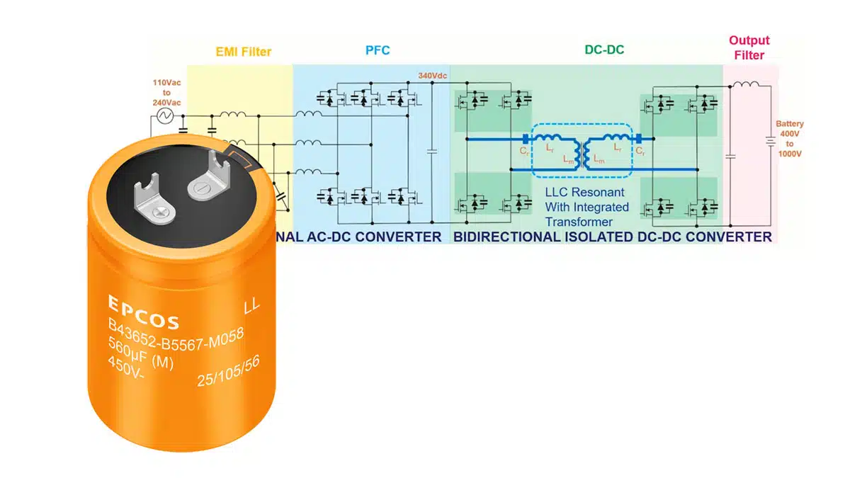
With the increasing market for electrified vehicles (EVs), the demand for on-board chargers (OBCs) is growing fast. OBCs open up the possibility to charge the car not only at fast-charging DC stations but also with AC sources in a reasonable time. Such systems are currently going up to 22 kW with operating voltages up to 800 V.

RelatedPosts

TDK Extends Range of Industrial Single Pair Ethernet (SPE) Inductors

TDK’s High-Impedance Multilayer Common Mode Filters Mitigates Noise Issues in Automotive Interfaces

TDK Releases Industry’s Highest Rated Current Chip Beads for Automotive Power Supply EMC Compliance

The function of the OBC is to convert the AC voltage from an external source to a specific DC voltage that is based on the requirements of the battery management system. By this, a battery-saving and fast charging process can be reached. Especially in remote areas without sufficient fast DC charging infrastructure, OBCs are essential to make EVs more attractive.

Due to the complexity of such systems, the OBC needs a certain bulk capacitance to stabilize the DC voltage that is charging the battery. Aluminum electrolytic capacitors are an attractive solution here since they can fulfill the key requirements, such as high voltage ratings of up to 500 V, large capacitance of up to 820 µF and high ripple current capabilities at an operating temperature range of -40 °C to 105 °C.

Figure 1. On-board charger challenges; source: TDK

Challenges for aluminum electrolytic capacitors in on-board chargers

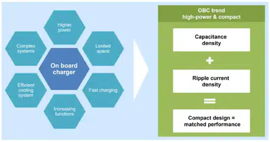
The DC link capacitor does not only have to fulfil the capacitance requirements of the system, but it also must withstand the continuously increasing ripple currents since the power densities of the OBCs are steadily rising.

As a result, higher power losses appear that heat up the complete system which can cause performance degradation and reduced lifetime. Therefore, being competitive inevitably requires a cooling system that is also connected to the DC link capacitors.

To cover these requirements, TDK developed the new large-size series B43652* for OBC applications that is optimized for base cooling and perfectly combines all of the above-mentioned characteristics.

The reason for thermal management

The right choice of the DC link capacitor depends on several parameters. The rated voltage (VR) results from the operating voltage of the OBC and shall cover the average plus peak ripple voltage. For systems >500 V, in series connected capacitors can be considered. The rated ripple current IR, the required lifetime and the operating temperature range arise from the mission profile of the OBC. The operating temperature range shall cover the expected ambient temperatures across the complete service life.

While some requirements are given and can hardly be changed, some characteristics can be optimized either by the supplier or the customer. The lifetime of an aluminum electrolytic capacitor is mainly influenced by its core temperature. Generally said, high ripple currents and increased ambient temperatures heat up the capacitor significantly and therefore reduce the lifetime.

Figure 2. Key factors influencing aluminum capacitors’ useful life; source: TDK

Based on the Arrhenius equation as a rule of thumb, one can consider a lifetime reduction of 50% when increasing the core temperature by 10 K. To reduce core temperatures under the same load conditions, the ESR of the component can be reduced and the thermal management can be optimized. With the B43652* series, TDK developed a large-size capacitor that has both a very low ESR and an improved internal thermal resistance across the full lifetime.

With an external cooling system providing an efficient heat transfer between the capacitor’s can bottom and the heatsink, customers can get the maximum out of these capacitors, i.e. a high ripple current capability for a significantly increased lifetime. From an economic point of view, such optimizations are always to be preferred compared to using either more capacitors in parallel or capacitor designs with longer rated lifetime.

Inner design in the context of capacitor cooling

The inside of an aluminum electrolytic capacitor contains a winding element that naturally has a much higher thermal conductivity in the axial than in the radial direction. To gain a base cooling option, this thermal conductivity in the axial direction was further improved for the B43652 series of compact snap-in aluminium capacitors.

Figure 3. Internal design of an aluminum electrolytic capacitor and its influence on heat dissipation; source: TDK

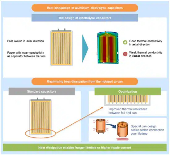
A direct metal contact between the winding element and the can bottom decreases the thermal resistance from hotspot to can and the improved stability of the can bottom itself avoids bulging over lifetime that would impair this thermal connection. As the bottom side of the capacitor usually contains a pressure relief vent that a heatsink would block, it was shifted to the side wall of the capacitor. Overall, the new B43652 series of TDK is a side-vented large-size capacitor targeting OBC applications with a base-cooling option.

Figure 4. Comparison of Rth values of a 35 x 40 mm large size capacitor with bottom-vented (left) and side-vented design (right); Source: TDK

The improvement of these design changes can be seen in Figure 4. For a standard 35 x 40 mm capacitor the internal thermal resistance in the axial direction is 4.49 K/W while it is reduced to 0.6 K/W for the improved side-vented design of the B43652 series. The overall thermal resistance from core to ambient is also reduced by 20% from 15.1 K/W to 12 K/W due to the metal contact between the winding element and the can bottom.

In Figure 5, a comparison of thermal simulations (temperature and heat flux) of the bottom-vented design with natural connection (left) and the side-vented design with base cooling (right) is presented.

When applying 1 W per capacitor at 85 °C ambient temperature, a core temperature of 106 to 109 °C is reached for the non-cooled version.

Looking at the same scenario with the side-vented design and a base cooling, considering a heatsink temperature of 85 °C, the core temperature of the capacitors is increased only by 3 K to 88 °C. This is approximately 20 K lower than the non-cooled design and means a lifetime increase of roughly 200%.

Figure 5. Thermal simulation of a capacitor bank considering the non-cooled standard design and side-vented design with cooling; Source: TDK

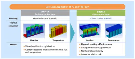
Comparing the heat flux simulations, it is visible that the base-cooled scenario transfers heat mainly via the can bottom. A gradient in the axial direction can be seen, presenting weak heat transfer on the PCB side and strong heat transfer on the bottom side.

The non-cooled version presents a gradient in the other direction, heat transfer mainly happens in the direction of the PCB. Hence, the non-cooled design shows a weak heat flux through the bottom side and besides this also an asymmetric heat flux for the center capacitors.

Further, while the non-cooled version displays a spread across the core temperatures, which means a thermal asymmetry with center capacitors having higher core temperatures, the base-cooled version does not have such a spread, resulting in a significantly reduced escalation risk.

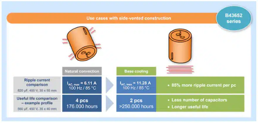
The overall improvements that can be reached in an OBC application are presented in Figure 6. Comparing two B43652 capacitors of the same size, rated voltage and rated capacitance, the base-cooled capacitor can withstand 85% more ripple current than the same design with just natural convection.

While the capacitor with natural convection reaches a maximum ripple current IAC,max of 6.11 A, the base-cooled version reaches 11.28 A. Furthermore, for the same load conditions, two base-cooled capacitors can withstand the mission profile almost two times longer than four non-cooled capacitors.

Figure 6. Comparison of natural convection and base cooling of aluminum capacitors; Source: TDK

Based on these results, it is clearly evident that TDK’s large-size capacitors of B43652* series are optimized for OBC applications with a base cooling option and can significantly reduce the number of pieces in the DC-link capacitor bank, making this series not only technically but also economically interesting.

Source: TDK

Related Posts

Capacitors

Investigating Modeling Techniques of Class II Ceramic Capacitors Losses for High Voltage and Current Applications

15.3.2023
2
Inductors

Premo Unveils New series of 11kW 3-Phase On-Board Charger Transformers

15.3.2023
3
Inductors

TAIYO YUDEN Releases 150C Automotive Power Inductors

15.3.2023
1

Upcoming Events

Mar 15
March 14 @ 12:00 - March 16 @ 14:00 EDT

Design and Test of Non-Hermetic Microelectronic

Mar 19
March 19 - March 23

APEC 2023

Mar 22
14:00 - 15:00 CET

Parasitic Components in Power Converters – Fundamentals and Measurements Rohde & Schwarz Webinar

View Calendar

Popular Posts

  • Ripple Current and its Effects on the Performance of Capacitors

    3 shares
    Share 3 Tweet 0
  • What is a Dielectric Constant of Plastic Materials ?

    4 shares
    Share 4 Tweet 0
  • Understanding High-Precision Resistor Temperature Coefficient of Resistance

    0 shares
    Share 0 Tweet 0
  • How to Choose the Right Inductor for DC-DC Buck Applications

    0 shares
    Share 0 Tweet 0
  • Capacitor Selection for Coupling and Decoupling Applications

    28 shares
    Share 28 Tweet 0
  • Why Low ESR Matters in Capacitor Design

    0 shares
    Share 0 Tweet 0
  • Leakage Current Characteristics of Capacitors

    0 shares
    Share 0 Tweet 0
  • Capacitor Losses (ESR, IMP, DF, Q), Series or Parallel Eq. Circuit ?

    0 shares
    Share 0 Tweet 0

Newsletter Subscription


PCNS Call for Papers !

Archive

2022
2021
2020
2019
2018
2017

Symposium

Passive Components Networking Symposium

Passives e-Learning

Knowledge Blog

  • Home
  • Privacy Policy
  • EPCI Membership & Advertisement
  • About

© EPCI - Premium Passive Components Educational and Information Site

No Result
View All Result
  • Home
  • News
  • Video
  • Knowledge Blog
  • Preferred Suppliers
  • Events

© EPCI - Premium Passive Components Educational and Information Site

Welcome Back!

Login to your account below

Forgotten Password?

Retrieve your password

Please enter your username or email address to reset your password.

Log In
This website uses cookies. By continuing to use this website you are giving consent to cookies being used. Visit our Privacy and Cookie Policy.