


Source: Microwaves & RF article
by Mario D’Auria, John Greenwood, and Chris Hunt at Pireta, and Martin Salter and Nick Ridler at National Physical Laboratory (NPL). This novel technology allows for the creation of conductive tracks on fabric, making it a potential solution for a wide range of wearables.
In the RF world, a significant effort has been made to develop high-performance substrates to reduce losses and extend frequencies. While many high-performance substrate options are now on the market, most can be classified as rigid, or at best, semi-flexible. In fact, in this high-performance race, many have overlooked all of the markets in which extreme performance and high frequencies were not required. Rather, these markets would have benefitted from new mechanically compliant substrates.
In this era when technology is becoming smaller and cheaper, more are looking to wearable technology as a predominant field of interest for markets ranging from medical to military to fitness. Conventional manufacturing technology that uses “rigid” components requires a great deal of effort to miniaturize the overall component. However, this kind of approach doesn’t lend itself to RF applications in which the overall geometry depends on the frequency and imposes certain limitations that cannot be easily overcome.
In fact, many of the wearable devices that require wireless communications are large and bulky, limiting the freedom of movement, or at least the comfort, of the user. Here, we want to illustrate how a technology that allows for the creation of conductive tracks on fabric can provide both freedom of space and design while maintaining comfort and flexibility for the final user.
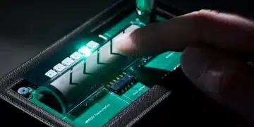
Pireta’s technology process, which makes it possible to create conductive tracks and patterns on textiles, is suitable for both natural and synthetic fibers. This proprietary process involves five steps: cleaning, sensitizing, seed layer printing, electroless coating, and passivation. These are all immersion processes except for the seed layer printing, which allows for the geometrical freedom in creating the desired pattern.
Designed to be scalable, this process is amenable to large-scale production, sharing some processing steps with roll-to-roll digital printing. The fabric is coated with metal at the fiber level, making it conductive without losing its inherent properties like handle, drape, stretch, and breathability.
One of the fundamental structures involved with evaluating the suitability of a process for RF applications is transmission lines. Thus, short transmission-line sections were fabricated on cotton drill fabric using the Pireta process.
The transmission lines consisted of two 5-mm wide tracks with 2 mm of separation between them. Two different versions were fabricated, one with two 50-mm-long transmission lines and another with two 80-mm-long transmission lines. This kind of transmission line, known as a coplanar strip, is the electromagnetic (EM) counterpart of a coplanar waveguide.1 They were manufactured by the deposition of a silver seed layer using the Pireta process, followed by copper electroless plating and finally a silver layer passivation.
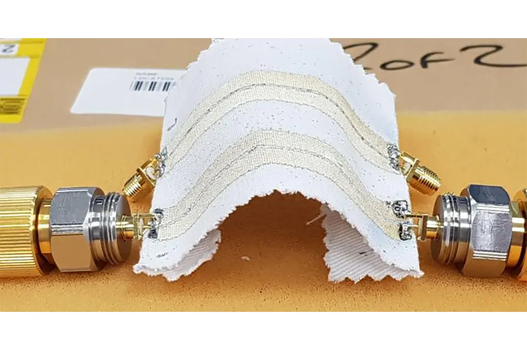
After fabrication, geometrical measurements were taken again, and the track width was found to be 5.5 mm with a gap of 1.7 mm. Subsequently, the piece of fabric was hemmed, allowing the SMA female coaxial connectors to be soldered to the ends (Fig. 1). As this technology uniformly coats the fibers with metal, the fabric surface is suitable for soldering using common lead or lead-free solder, depending only on the fabric’s tolerance to high temperatures.

1. The 80-mm transmission lines with SMA connectors are connected to the vector-network-analyzer cables.
VNA Measurements
Measurements were carried out at the National Physical Laboratory using a Keysight PNA-X vector network analyzer (VNA). The test frequency was varied between 10 MHz and 10 GHz. The cables connected to the VNA used precision 3.5-mm connectors, which are rated up to 33 GHz.2 (SMA connectors are commonly used up to approximately 12 GHz, although they can be used at higher frequencies.)3 A short-open-load-thru (SOLT) calibration was carried out before performing the measurements.4 The measurement results (i.e., S-parameters) for one of the 50-mm-long lines and one of the 80-mm-long lines are shown in Figures 2 and 3, respectively.

2. These are the S-parameters (a and b) for the 50-mm-long line.

3. The S-parameters (a and b) for the 80-mm-long line are plotted.
For both lines, the values of the reflection parameters (S11 and S22) reveal relatively poor matching above 100 MHz. Due to the resolution limitations of the printing process, and this being a preliminary test, the impedance of the lines was deliberately not optimized. However, it’s feasible that implementing an impedance transformer could solve this matching problem. Furthermore, in both cases, S11 and S22 are almost identical at each frequency, suggesting that the soldering process for the SMA connectors has good repeatability.
The transmission parameters (S12 and S21) for both lines show acceptable performance up to 2 GHz and possibly beyond, once the design has been optimized to reduce the mismatch from the VNA test port connectors. The transmission losses, summarized in terms of S21 at specific frequencies for all four lines, are shown in the table.

S21 measurements were taken at specific frequencies for the four lines.
Using the formula below:5

it’s possible to calculate α’d (i.e., the attenuation per unit length after correcting for the mismatch loss) for the two lines. The results illustrated in Figure 4 show very low attenuation per unit length for electrically short sections of line, i.e., approximately 0.20 dB/cm from 10 MHz to 100 MHz and 0.32 dB/cm at around 1 GHz.

4. Calculated attenuation per unit length is given for the 50- and the 80-mm-long lines.
Increase in Metallization
To improve the performance of these RF transmission lines, a new set of lines was manufactured. This time, a copper electroplating step was added after the passivation step to reduce the ohmic losses. These lines had a similar external appearance as the previously manufactured lines, with a marginal increase in stiffness.
Figure 5 shows the measured attenuation per unit length for both the set of transmission lines manufactured using the standard Pireta electroless (EL) process and the new set of lines fabricated with an extra layer of electroplated (EP) copper. Design and testing parameters were kept the same to allow for a direct comparison between the results. The electroplating parameters were 50 mA/cm2 for 10 minutes.

5. An attenuation per unit length comparison between the electroless (EL) and the electroplated (EP) 50- and 80-mm lines was performed.
The results show a significant improvement over the frequency range of 10 to 100 MHz. Above 100 MHz, the losses gradually start to increase. Nonetheless, the results continue revealing a 0.2 dB/cm improvement in comparison to the electroless lines, resulting in a loss per unit length of 0.3 dB/cm at 1 GHz.
It’s believed that this increase in loss is due to inevitable geometrical imperfections in the lines, the rough edges of the printed features caused by the weaving pattern, and the roughness of the fabric itself. It’s logical to assume that a better design and a finer fabric would improve the results. The suitability of the Pireta technology depends on the requirements of the application. By copper electroplating, the usable frequency can be extended to at least 1 GHz.
Tissue Proximity

6. Attenuation is revealed in the cases of contact with human tissue (fingers), with a spacer between the tissue, and with the printed fabric folded between the transmission line and the tissue.
For the Pireta technology to be usable on clothing, it must be suitable for use when in contact with skin. It’s to be expected that the body, being a lossy medium, would degrade the performance of the transmission lines. This can be seen in Figure 6, when three fingers were placed directly under the transmission lines (Fig. 7a).

7. The 80-mm transmission lines were tested with a hand underneath (a), an insulation layer between the hand and the lines (b), and another line folded underneath and a hand below (c). (See Figure 6 for the results).
Similar degradation in performance was observed when an insulating layer was interposed between the fingers and the lines (Fig. 7b). However, if another layer of conductive fabric is placed underneath the lines, the performance remains approximately the same (Fig. 7c). This demonstrates that, given the right design, the human body’s effect on performance can almost be removed.
Non-Flat Fabric

8. Four different test conditions were applied to the fabric transmission lines: U-bend (a), wiggle (b), misaligned (c), and 180° twist (d).
Finally, the lines were tested under different distortion conditions of the fabric substrate (i.e., flat, U-bend, wiggle, misaligned, and twisted) (Fig. 8). Figure 9 shows the results for all of these test conditions. There’s very little variation in the measured performance as a result of these different test conditions, with only slightly larger losses in the wiggle configuration. This may be due to the formation of coupling between different sections of the line, as suggested by the shift in the observed peaks for these transmission lines.

9. This is the measured attenuation per unit length for all five test conditions: flat, U-bend, wiggle, misaligned, and twist.
Results and Future Work
The reported results show the feasibility of a process to produce transmission lines on fabric for RF applications to at least 1 GHz and perhaps beyond. This corresponds to the radio communications range of frequencies (AM: 0.3 to 3 MHz, FM: 30 to 300 MHz), RFID (3 to 30 MHz), and wireless communications (Wi-Fi/Bluetooth: 2.4 GHz, satellite radio: 1.4/2.3 GHz). With the possibility of removing the effect of human tissue on the performance of these transmission lines, this approach could be used for wearable RF applications. This is further supported by the observed resilience to fabric distortion, which had very little effect on the measured loss in the lines.
Future steps will include optimizing the planar structure to improve the reflection losses. In addition, the dielectric constant of the fabric substrate, the thickness of the conductive lines, and the non-uniform current path compared with conventional solid metal track lines will all be considered.
Conclusions
It’s been demonstrated that the Pireta technology, though still in its infancy, can deliver an e-textile technology that meets the RF requirements of many telecommunications applications, including the sub-6-GHz end of the 5G spectrum. At the same time, the technology does not affect the textile characteristics of the handle, drape, and breathability. This exciting combination of properties offers important opportunities in many application areas and potentially opens doors to new product developments.
References
- R. Garg, I. Bahl, M. Bozzi, Microstrip lines and slotlines. London: Artech House, 2013, p. 376-377.
- IEEE Std 287-2007, “IEEE Standard for Precision Coaxial Connectors (DC to 110 GHz).”
- IEC 60169-15:1979, “Radio-frequency connectors. Part 15: R.F. coaxial connectors with inner diameter of outer conductor 4.13 mm (0.163 in) with screw coupling – Characteristic impedance 50 ohms (Type SMA).”
- S. Rehnmark, “On the Calibration Process of Automatic Network Analyzer Systems,” IEEE Trans. On Microwave Theory and Techniques, April 1974, p. 457-458.
- F. L. Warner, A. E. Bailey, “Attenuation measurement” in Microwave Measurements, London, U.K.: IEE, p. 132-134, 1989.