


Source: Microwave Product Digest article
by Pierre Mars, Vice President, Quality & Applications Engineering, CAP-XX (Australia) Pty Ltd
Until CAP-XX announced its 3V range of prismatic cells, 3V cells were only available in cylindrical cans due to the more robust construction of cans enabling a wider choice of materials inside the supercapacitor. CAP-XX has determined a set of materials that have good capacitance, ESR, temperature and life performance at 3V in a thin prismatic package.
Supercapacitors are used to support peak power and/or to supply backup power. For peak power applications, the load demands more power than the energy source can provide, but the load only operates periodically or sporadically with a low duty cycle, so the average load power is < the power that the energy source can deliver. Typical peak power applications include: 1) data collection and transmission by wireless sensors and automatic meter reading, 2) transmission for remote activation such as key fobs, 3) a vibration alert in wearables, and 4) driving actuators such as solenoids for valves, locks etc. In backup power applications, the supercapacitor has enough energy and can deliver the power required to support the system to enable graceful shutdown or to set a lock or valve in a safe state in case of power failure, or to provide ride-through capability in case of brief interruptions such as battery contact chatter or when someone drops a handheld terminal.
Supercapacitors do not have a dielectric; they are electrical double layer capacitors (EDLC) with ions in solution in an electrolyte at the surface of a highly porous carbon electrode. There is a porous separator between the electrodes that allows the ions to pass through for charge transport but prevents the two electrodes shorting. The charge separation distance is effectively the width of the ion, measured in nm. The high surface area of the carbon, typically > 2000m2/gm, affords a massive charge storage area which, coupled with the minute charge separation distance, makes the capacitance “super.” Since there is no dielectric, their charge voltage is limited by the electrochemistry of the electrolyte and electrodes. This makes them low-voltage devices. As materials have improved, voltage has increased, from typically 2.3V/cell in 2000 to 2.5V, then 2.7V or 2.8V and recently up to 3V.
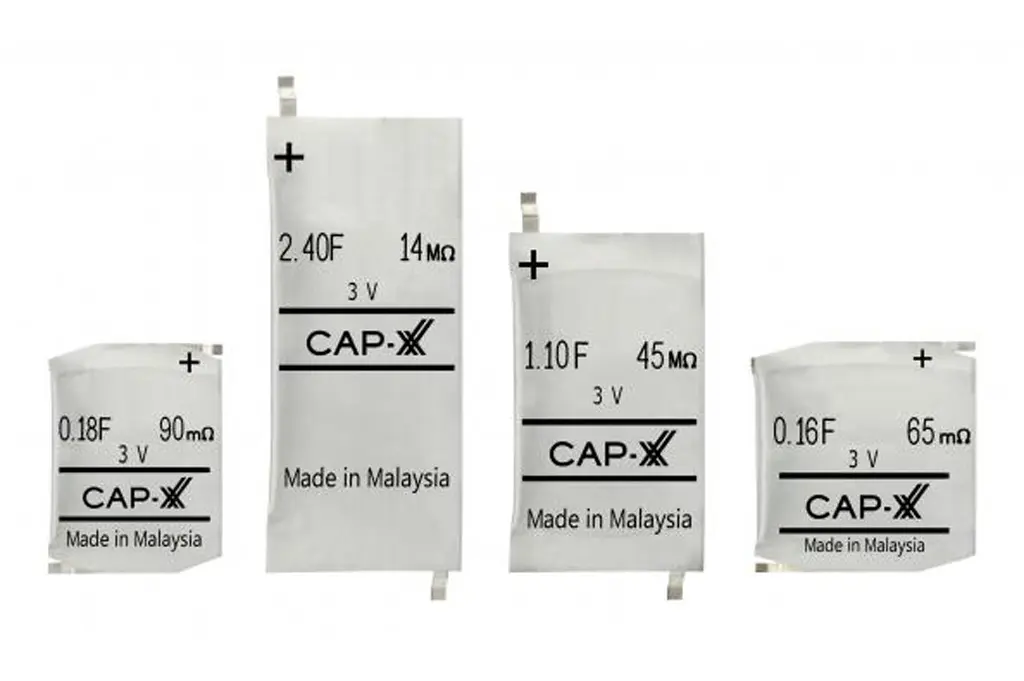
Until CAP-XX announced its 3V range of prismatic cells, 3V cells were only available in cylindrical cans due to the more robust construction of cans enabling a wider choice of materials inside the supercapacitor. CAP-XX has determined a set of materials that have good capacitance, ESR, temperature and life performance at 3V in a thin prismatic package. Many applications with a low-power energy source, such as a 3V coin cell, or an energy harvester such as a small solar cell, require a slim elegant form factor. Examples include key fobs, wearables, and sensors on a living room wall. The CAP-XX 3V parts will be available in the same form factors as our current prismatic range. See PR on release of CAP-XX prismatic parts here.
Drive to Reduce Power
There has been a major drive in recent years to reduce power. As part of this drive, supply voltages for many applications have been reduced to operate in the 1.8V – 3V range where previously higher voltages in the order of ~3.6V were required. Many IoT, key fob and wearable applications are powered by lithium 3V coin cells such as CR2032. These cells have reasonable energy at ~220mAh, but have trouble delivering the peak pulse power required for data collection and transmission or providing alerts in wearables. The typical coin cell internal resitance, RB, is ~10Ω and is rated for pulse currents ~30mA. Figure 1 shows the voltage drop for a CR2032 coin cell in response to a 30mA step current. The voltage drop after 100µs, when the voltage has stabilized, is 180mV, so the battery impedance is 180mV/30mA = 6Ω.
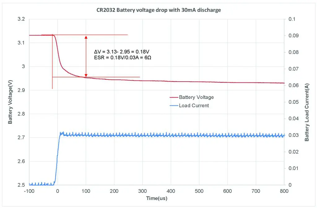
Figure 1: Internal resistance of a CR2032 coin cell
For a typical 3V coin cell with ~10Ω resistance, even supplying 25mA for Bluetooth® transmission results in a 250mV drop. To supply a 100mA pulse, such as when driving a vibration motor or longer range RF transmission, the battery voltage would drop by 1V. This means that for many applications, coin cells cannot provide the necessary power, or, the battery voltage drop when supplying this power will result in a premature under-voltage lockout with plenty of energy still left in the battery.
The simplest solution to overcome this problem is to place a supercapacitor between the battery and the load. Supercapacitors are ideal power buffers between a low-power energy source such as a small battery or energy harvester and a higher-power load. Their low ESR makes them able to deliver high power to the load and their high C supports the peak power bursts for their duration. The battery charges the supercapacitor at low average power and the supercapacitor delivers the high burst power to the load. Given the small thin industrial design of many of these applications, only a thin prismatic supercapacitor cell is suitable, such as a CAP-XX HA130F, which is 800mF capacitance and only 80mΩ Equivalent Series Resistance (ESR), or a CAP-XX HA114T, which is only 0.7mm thick, 120mF and 125mΩ ESR. Until now, these cells have only been rated to 2.7V. This required a low-dropout (LDO) voltage regulator between the battery and supercapacitor cell to step the supercapacitor charge voltage down to 2.7V. In contrast, the new 3V cell can be placed directly across the battery, as shown in Figure 2.
RLIM is an optional current limit resistor to limit the inrush current to the supercapacitor when it is first charged. The supercapacitor steady state voltage = Vbatt – (RB+RLIM) x average charge current from the battery to supercapacitor. Figure 3 shows the voltage and current supplying a SensorPuck BLE sensor from a CR2032 coin cell with and without a CAP-XX supercapacitor directly across the battery.
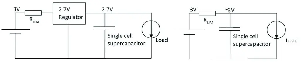
Figure 2: Battery voltage stepped down to 2.7V for supercapacitor (left); supercapacitor directly across the battery (right)
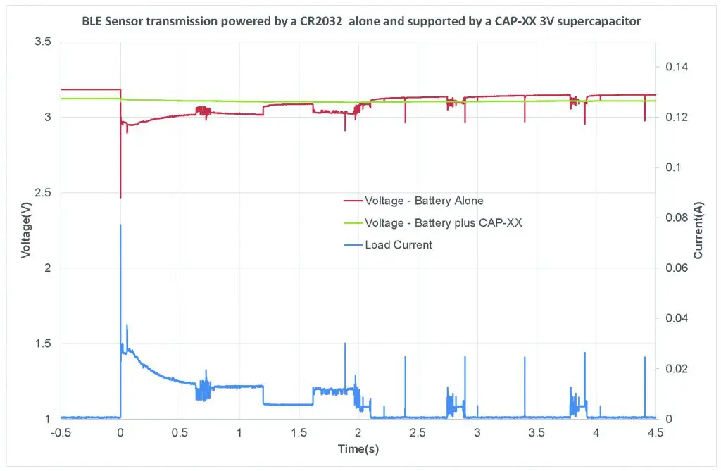
Figure 3: Initial current peak when a microcontroller and Bluetooth® sensor power on is ~80mA
Figure 3 shows the initial current peak when a microcontroller and Bluetooth sensor power on is ~80mA. After that, the current peaks at ~25mA every tranmsission. The battery voltage without supercapacitor support drops from 3.13V to 2.47V supplying the initial current and then drops 160mV from 3.13V to 2.97V supplying subsequent transmisissions. The 3V cell used to support the battery in Figure 3 has ESR = 18mΩ and capacitance = 2.4F. The green trace in Figure 3 shows the load voltage with supercapacitor support. There are no discernable voltage drops during the data collection and transmission peaks. When steady state has been reached, after ~4s, the voltage between peaks is ~40mV lower with supercapacitor than in the case without the supercapacitor. This is because the battery is supplying average charge current to the supercapacitor between peaks. Given that we have measured the internal resistance of this particular battery at 6Ω, this implies the battery is supplying an average current = 6.7mA. The supercapacitor has reduced the voltage drop supplying the load by 120mV from 160mV to 40mV. This allows all the energy to be extracted from the battery as shown in Figure 4. The battery alone supports the sensor puck for 279 hours while the battery supported by the 3V supercapacitor cell for 335 hours, or a 20% increase. The increase in battery run time will depend on the peak power drawn by the load, with the greater the peak, the larger the % improvement.
Supercapacitors are simple to charge—they will accept whatever current the source can provide. All that is required is over-voltage protection. With a 3V supercapacitor coupled with a 3V battery, over-voltage protection is inherent in the design. Since they use physical rather than electrochemical charge storage, they also have virtually unlimited cycle life and excellent charge/discharge efficiency, as shown in Equation 1.
In the sensor puck example, if a 3V 2.4F, 18mΩ supercapacitor is discharged at 25mA for 100mS, and charged at 5mA for 500ms, the round trip efficiency = 99.99%.
Only CAP-XX offers a 3V cell in a thin prismatic form factor that does not compromise the industrial design for wearables, key fobs and unobtrusive thin, flat sensors. The advantages of being able to use a 3V cell instead of a 2.7V cell include:
Savings in cost and size, since the 2.7V regulator is no longer required.
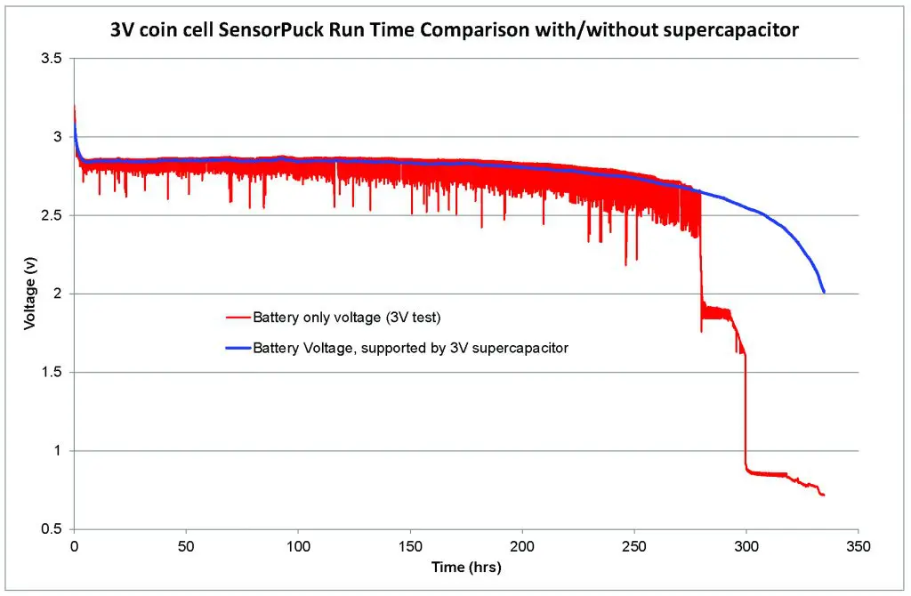
Figure 4: Supercapacitor allows more energy to be extracted from the battery
Reduced losses and improved battery run time:
- An LDO is required to step the voltage down from 3V to 2.7V, to charge a 3V cell. A 3V CR2032 coin cell has a typical capacity of 240mAh. If the LDO draws a quiescent current of 1µA, then this consumes 8.8mAh/yr, or ~4% of battery capacity per year.
- Consider a constant power load. If the battery voltage is stepped down from 3V to 2.7V then the load will draw 10% more current, so battery life will be 10% shorter
- Increased usable energy storage in the supercapacitor. For example, if an application operates down to 1.8V, then a 3V supercapacitor stores 42% more usable energy than a 2.7V one.
- Improved power density, by 23%.
Characteristics of CAP-XX 3V Cell
CAP-XX has characterized the cells, measuring ESR and capacitance over the -40°C to +70°C temperature range, leakage current, frequency response, and successfully meeting the IEC 62391 requirement for endurance at 3V, 70°C.
Capacitance & ESR
We measured DC ESR by charging 5 cells to 3V, holding them at 3V for an hour and then applying a 100mA discharge current and measuring the time for the cell to discharge from 2V to 1V. Figure 5 shows all the cells measured at 2.4F. We measured DC ESR by applying a 1A step current and measuring the voltage drop when the current has settled, 50µs after the current step was applied. Figure 5 shows the cells measured 18mΩ ESR. These 3V cells are similar in performance to the current CAP-XX HS130F, 2.75V, 2.4F, 25mΩ cell with a power density = 67.1KW/L and energy density = 2.24Wh/L. Figure 5 also shows that the cells are tightly grouped in their performance.
Low Leakage Current
Leakage current is very important in any application where the supercapacitor is across a battery, particularly a non-rechargeable battery. 1µA leakage current will drain 8.8mAh per year of charge from the battery. CAP-XX supercapacitors typically draw ~1µA/F. Figure 6 shows the leakage current over time when the CAP-XX cells are held at 3V.
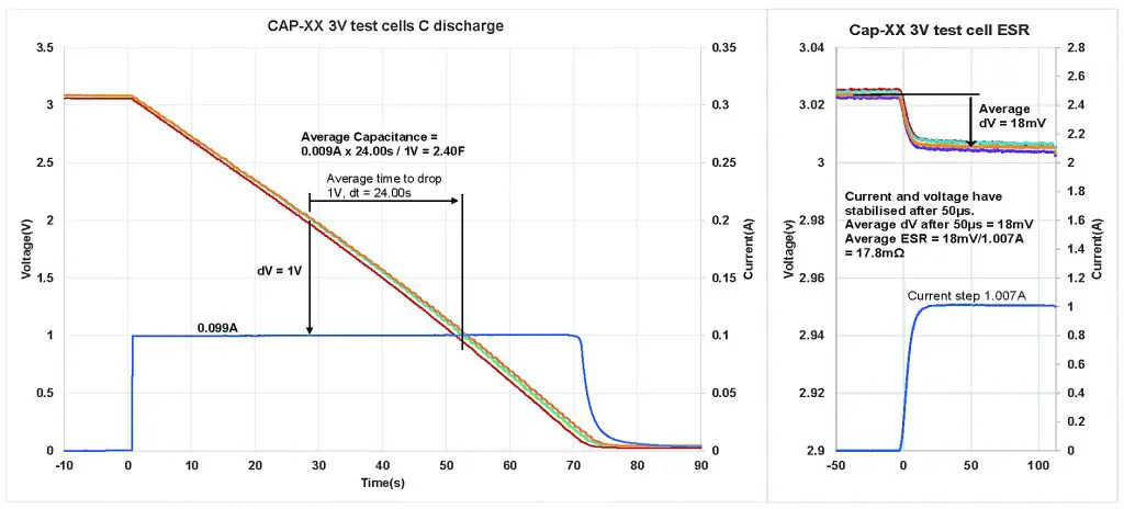 Figure 5: Measurement of DC capacitance and ESR for 5 cells.
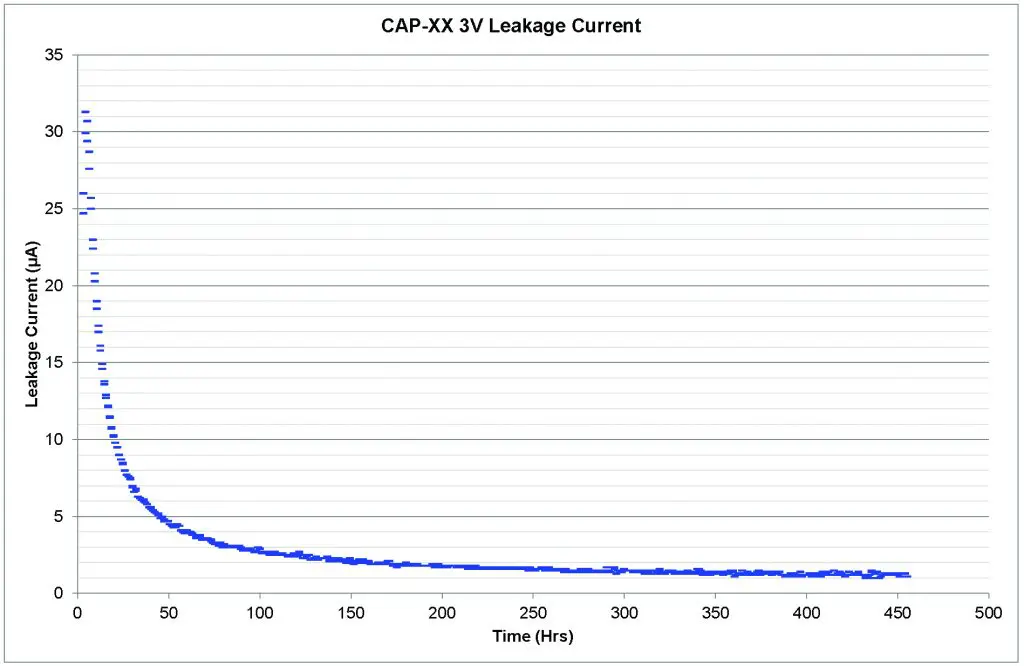
Figure 6: Leakage current over time at 3V
The leakage current decays over time until it reaches an equilibrium level. All organic electrolyte supercapacitors behave in this way. In the case of the CAP-XX cells, the leakage current settles to just over 1µA after 400hrs, which is very low for a 2.4F cell. It should be noted that in most applications, where the supercapacitor only undergoes a shallow discharge to support the peak-power load, as in Figure 3, the leakage current does not reset to a high value, but only increases slightly and returns to its equilibrium value quickly.
Variation in C & ESR with Temperature
Another major benefit of using a supercapacitor to support a battery is the wide temperature range of operation for a supercapacitor, particularly at low temperatures when battery internal resistance increases significantly, limiting any power the battery can deliver. Figure 7 shows the variation with temperature for C and ESR, normalized to temperature at 23°C. At -40°C, ESR is only double the room temp ESR, so in the case of the CAP-XX cells, this is only 36mΩ, so these cells can support high current peaks at extreme low temps. This allows outdoor applications, e.g. wearables, key fobs and meter reading, to operate in cold winter temperatures.
Frequency Response and Effective Capacitance
Supercapacitors are low-frequency devices. This is shown in Figure 8, where the 3V cell magnitude plot shows capacitance starts rolling off at ~3Hz and the phase plot is at -45° at 3Hz. At first glance, this poor frequency response may lead to a design engineer assuming these cells will not support very short peak power bursts of a few milliseconds or even sub milliseconds. In fact, CAP-XX supercapacitors support short pulses very well. This is because although for short pulses the capacitance available is << DC capacitance, you only need << capacitance to support a short pulse. CAP-XX has developed the concept of “effective capacitance,” or how much capacitance as a fraction of DC capacitance you see for a given pulsewidth. This is shown in the effective capacitance curve for the CAP-XX 3V cells in Figure 9.
Figure 9 shows that for a constant current pulse of 30s, you see 100% of DC capacitance and for a 1ms pulse you see 17% of DC capacitance. Table 1 shows the effective capacitance for a range of pulsewidths from Figure 9.
| Pulse Width | % of DC Capacitance |
| 30s | 100% |
| 10s | 98% |
| 1s | 90% |
| 0.1s | 78% |
| 0.01s | 35% |
| 0.001s | 17% |
| Table 1: Effective capacitance for a range of pulsewidths from Figure 9 | |
All CAP-XX datasheets include an effective capacitance graph. This enables a quick calculation for the voltage drop when supporting a constant current pulse, rather than having to resort to a SPICE model. As an example, consider a 0.5A, 10ms pulse. From Figure 5, the DC capacitance for the 3V cell is 2.4F and DC ESR is 18mΩ. Voltage drop at the end of the pulse = 18mΩ x 0.5A + 0.5A x 10ms/(35% x 2.4F) = 15mV. The voltage drop at the end of a 1ms, 0.5A pulse = 18mΩ x 0.5A + 1ms/(17% x 2.4F) = 10mV. Despite a frequency response showing capacitance rolling off at 3Hz, the CAP-XX 3V cell supports pulses down to 1ms and shorter. For short pulses, the total voltage drop is dominated by ESR x pulse current.
Long Life
Life is an important consideration, with supercapacitors having to last years in some applications. CAP-XX 3V cells have been tested at 3V, 70°C, meeting the IEC 62391 requirement for endurance. Figure 10 shows that the 3V cells easily meet the IEC endurance requirement of C loss < 20% and ESR rise < 4 x initial ESR after 1000 hours at 70°C, 3V. The cells had a C loss of ~10% and an ESR increase of ~2x.
Initially, the CAP-XX range of 3V cells will be available in our current range of footprints:
A: 20mmx 18mm
W: 28.5mm x 17mm
S: 39mm x 17mm
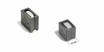
Thickness ranges from 1mm–2mm, depending on capacitance and ESR. The first 3V cells will be in the S footprint size. The A range fits conveniently over a 20mm diameter coin cell for ease of industrial design.
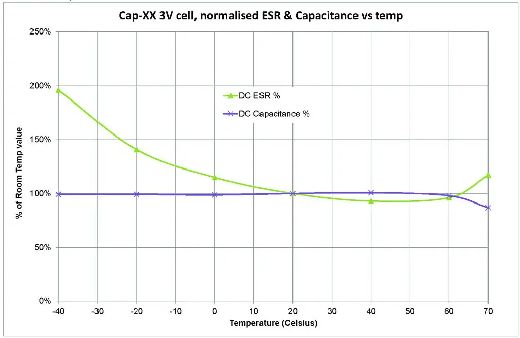
Figure 7: How DC capacitance & DC ESR vary with temperature
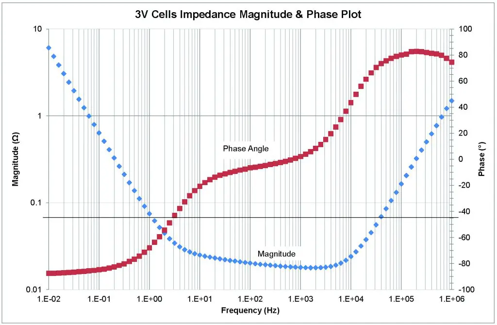
Figure 8: Frequency response
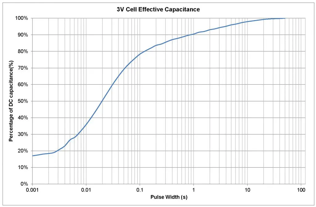
Figure 9: Effective capacitance of CAP-XX 3V cells as a function of PW

Figure 10: Endurance at 3V, 70°C
Summary
This article has reviewed how supercapacitors make ideal power buffers, enabling low-power energy sources to supply high peak power loads, the only constraint being that the average load power must be less than the power the source can suppy. CAP-XX has announced the first 3V thin prismatic cells, suitable for slim form factor applications, that can be connected directly across a 3V battery. This has reduced cost and space, and extends battery run time compared to placing a 2.7V regulator between the battery and a 2.7V supercapacitor. We have also reviewed the characteristics of the 3V cells which have low ESR and high C in a small package, resulting in very good power and energy density, and low leakage current so as not to excessively drain battery charge. We also reviewed the 3V supercapacitor’s frequency response and introduced the concept of effective capacitance, and showed that even though capacitance rolled off at 3Hz, these cells have excellent pulse response and can support sub-millisecond pulses.