
Passive Components Blog
No Result
View All Result
  • Home
  • News
    • All
    • Aerospace & Defence
    • Antenna
    • Applications
    • Automotive
    • Capacitors
    • Circuit Protection Devices
    • electro-mechanical news
    • Filters
    • Fuses
    • Inductors
    • Industrial
    • Integrated Passives
    • inter-connect news
    • Market & Supply Chain
    • Market Insights
    • Medical
    • Modelling and Simulation
    • New Materials & Supply
    • New Technologies
    • Non-linear Passives
    • Oscillators
    • Passive Sensors News
    • Resistors
    • RF & Microwave
    • Telecommunication
    • Weekly Digest
    Stackpole RNAN aluminium nitride thin-film chip resistors in 0603, 0805, 1206 and 2512 package sizes for precision high-power electronics

    Stackpole RNAN AlN Thin-Film Resistors Reach 6 W

    binder angled M12-A midmount panel-mount PCB connector for centric board mounting, showing compact front-facing industrial connector geometry

    binder Adds Midmount M12-A PCB Connectors for Slim Sensors

    Bourns PST065 and PST10 Series compact incremental potentiometers with hollow shafts for rotary position feedback

    Bourns Expands Compact Incremental Potentiometer Offering

    Wk 35 Electronics Supply Chain Digest

    Samsung MLCC Revenue Seen Above KRW 8T by 2027, Murata EOL Actions Reshape Supply

    ROHM SDR01 high anti-surge thick-film chip resistor in 1005 metric 0402 package with 0.33 W rated power

    ROHM Introduces Anti-Surge 0402 Resistors Rated at 0.33 W

    ECIA Industry Pulse Q3 2026 chart showing passive components, semiconductors and electro-mechanical component market sentiment and lead-time pressure

    ECIA Industry Pulse Moderates as Passive Lead Times Tighten

    LG Innotek Demonstrates FC-BGA Substrates With Embedded Silicon Capacitors for AI Power Delivery

    On-Chip 3D-Printed Copper Microinductors: A New Route to Compact RF Electronics

    Trending Tags

    • Ripple Current
    • RF
    • Leakage Current
    • Tantalum vs Ceramic
    • Snubber
    • Low ESR
    • Feedthrough
    • Derating
    • Dielectric Constant
    • New Products
    • Market Reports
  • Knowledge Blog
  • Dossiers
    • AI Hardware Dossier
    • Automotive Dossier
    • Industrial Robotics Dossier
    • Power Converter Dossier
    • Capacitor Dossier
    • Resistor Dossier
    • Inductor Dossier
    • Circuit Protection Dossier
  • Suppliers
    • Who is Who
  • PCNS
    • PCNS 2025
    • PCNS 2023
    • PCNS 2021
    • PCNS 2019
    • PCNS 2017
  • Events
  • Home
  • News
    • All
    • Aerospace & Defence
    • Antenna
    • Applications
    • Automotive
    • Capacitors
    • Circuit Protection Devices
    • electro-mechanical news
    • Filters
    • Fuses
    • Inductors
    • Industrial
    • Integrated Passives
    • inter-connect news
    • Market & Supply Chain
    • Market Insights
    • Medical
    • Modelling and Simulation
    • New Materials & Supply
    • New Technologies
    • Non-linear Passives
    • Oscillators
    • Passive Sensors News
    • Resistors
    • RF & Microwave
    • Telecommunication
    • Weekly Digest
    Stackpole RNAN aluminium nitride thin-film chip resistors in 0603, 0805, 1206 and 2512 package sizes for precision high-power electronics

    Stackpole RNAN AlN Thin-Film Resistors Reach 6 W

    binder angled M12-A midmount panel-mount PCB connector for centric board mounting, showing compact front-facing industrial connector geometry

    binder Adds Midmount M12-A PCB Connectors for Slim Sensors

    Bourns PST065 and PST10 Series compact incremental potentiometers with hollow shafts for rotary position feedback

    Bourns Expands Compact Incremental Potentiometer Offering

    Wk 35 Electronics Supply Chain Digest

    Samsung MLCC Revenue Seen Above KRW 8T by 2027, Murata EOL Actions Reshape Supply

    ROHM SDR01 high anti-surge thick-film chip resistor in 1005 metric 0402 package with 0.33 W rated power

    ROHM Introduces Anti-Surge 0402 Resistors Rated at 0.33 W

    ECIA Industry Pulse Q3 2026 chart showing passive components, semiconductors and electro-mechanical component market sentiment and lead-time pressure

    ECIA Industry Pulse Moderates as Passive Lead Times Tighten

    LG Innotek Demonstrates FC-BGA Substrates With Embedded Silicon Capacitors for AI Power Delivery

    On-Chip 3D-Printed Copper Microinductors: A New Route to Compact RF Electronics

    Trending Tags

    • Ripple Current
    • RF
    • Leakage Current
    • Tantalum vs Ceramic
    • Snubber
    • Low ESR
    • Feedthrough
    • Derating
    • Dielectric Constant
    • New Products
    • Market Reports
  • Knowledge Blog
  • Dossiers
    • AI Hardware Dossier
    • Automotive Dossier
    • Industrial Robotics Dossier
    • Power Converter Dossier
    • Capacitor Dossier
    • Resistor Dossier
    • Inductor Dossier
    • Circuit Protection Dossier
  • Suppliers
    • Who is Who
  • PCNS
    • PCNS 2025
    • PCNS 2023
    • PCNS 2021
    • PCNS 2019
    • PCNS 2017
  • Events
No Result
View All Result
Passive Components Blog
No Result
View All Result

Energy Density, Power Density and Capacitor Energy Content

22.5.2026
Reading Time: 12 mins read
A A

This article describes capacitor energy content, what energy can be stored and delivered by the capacitor and what forces present inside a capacitor. It also describe basic concepts of capacitor energy density and power density and their impact on capacitor performance.

Energy density and power density are two crucial yet distinct metrics in the field of energy storage. Understanding the differences between these two metrics is essential for designing efficient energy storage solutions.

RelatedPosts

ESR of Capacitors, Measurements and Applications

Degradation of Capacitors and its Failure Mechanisms

Backup Capacitors – Supercapacitor

Key Takeaways

  • Capacitor energy density measures how much energy a capacitor can store per unit mass or volume, crucial for applications where space is limited.
  • Power density indicates how quickly a capacitor can deliver energy, impacting performance in fast-response applications like lasers or camera flashes.
  • High energy density benefits long-term storage, while high power density allows for rapid energy transfer, necessitating a design balance.
  • Capacitance and voltage determine the energy stored in capacitors, while equivalent series resistance (ESR) affects their power density.
  • Understanding the forces in magnetic and electrostatic fields is vital for analyzing capacitor behavior under high voltage conditions.

Comparing Energy Density and Power Density 

Energy density describes the amount of energy stored in a mass (Wh/kg or J/kg) or volume (Wh/L). High energy density implies the system can store a lot of energy in space- and weight-constrained spaces. This is particularly useful in applications like mobile devices and electric vehicles where board space is a luxury and long-term energy storage is critical for operational efficiency. 

While frequently mentioned together in energy storage discussions, energy density and power density represent distinct performance characteristics. Power density describes how quickly energy can be delivered or absorbed into a system in W/kg or W/m3. High power density tells us a system can release or accept energy at a fast pace. This characteristic best serves applications that require quick bursts of energy like camera flashes or industrial lasers. 

In short, energy density focuses on storage capacity while power density measures the rate of energy transfer, and systems designers are expected to balance the two. For example, batteries with high energy density may not be able to deliver energy as quickly as supercapacitors, which are known for their high power density. 

Capacitor Energy Content and Power Density Math 

The energy stored in a capacitor is expressed using:
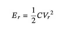
where

  • C is capacitance
  • Vr is the voltage rating of the capacitor.

To find the volumetric energy density of a capacitor, divide Er by volume: 
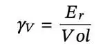
The power rating of a capacitor can be estimated from the rated voltage and current as :
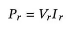
Power density is Pr  divided by volume: 
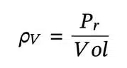
Alternatively, another approach to determining power density is to examine the impedance-matched condition, where the load matches the source impedance (i.e., the capacitor’s equivalent series resistance (ESR)). Under these conditions, we find: 
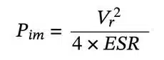
Then, power density is calculated as: 
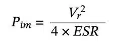
This method reveals that capacitors with high power density require a low ESR to maximize the rate of energy transfer. As a result, innovation in capacitor design focuses on optimizing capacitance and voltage within a compact volume while minimizing internal losses from ESR. 

Electromagnetic Fields Force action

Parallel current carrying conductors are surrounded by magnetic fields exerting forces on each other. If currents flow in the same direction the fields (and the conductors) attract each other. If the current flows in opposite directions they are repelling each other.
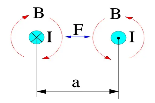
Figure 1. Magnetic force action, F, between conductors with a current flow, I. B = magnetic flux density.

If

  • the conductor length l is expressed in m,
  • the current I is expressed in A and
  • the distance a is expressed in m,

the force per meter between the conductors will be
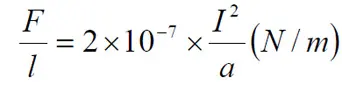
………………………[2]

According to the basic charge formula Q = C x V (As). If this expression is derived we obtain dQ/dt = I = C x dV/dt (A). Pulse loads are not unusual, especially in conditions with high voltage gradients, and thus high charging currents also occur which might cause appreciable magnetic fields between close lead patterns, for example.

Force action in electrostatic fields

Capacitors are typical examples of applications where electrostatic fields are applied. These fields can generate significant mechanical forces­. If we know the electrode distance d (m) it’s easy to determine the electric field strength E (V/m). Then we can outline the force per unit area, i.e. the pressure that the electrodes exert on the dielectric.

This image has an empty alt attribute; its file name is EQ-C1_22.jpg

……………………………….. [3]

Example. Suppose we have an oil impregnated paper capacitor with r = 5 and the dielectric = 15 m (0.6 mils) which is loaded with 250VAC. Then the instantaneous maximum pressure will be

This image has an empty alt attribute; its file name is EQ-C1_22b.jpg

0.1 kp/cm2 !

If we instead calculate on a 35 V solid tantalum capacitor with a typical and approximate dielectric thickness of 0.2 mm (0.008 mils) the formula gives at 30 V DC a pressure of

This image has an empty alt attribute; its file name is EQ-C1_22c.jpg

2 N/mm2 !

It is difficult to determine how much the dielectric is influenced by such forces, especially when the electrodes have such complex configurations. Electrostatic action of such forces here is of vital importance.

Electrostatic Force Potential Impact

We learned in the article about the energy stored in the capacitor, but what is also important and demonstrated is that there is enormous mechanical pressure between the electrodes once voltage is applied.

This can be considered in failure analyses if we have a solid, sharp impurity within the capacitor dielectric – it may degrade the insulator not only by inducing electrical conductivity/increasing leakage current, but also causing a mechanical damage to the dielectric due to the high electrostatic pressure between the electrodes. Hard and sharp micro-crystals in amorphous dielectric could be an example of such defects.

FAQ: Energy Density, Power Density and Capacitor Energy Content

What is energy density in capacitors?

Energy density is the amount of energy stored per unit mass or volume of a capacitor. It is typically measured in Wh/kg or Wh/L, reflecting how much energy can be packed into a limited space. High energy density is essential for efficient storage in mobile and compact devices.

What is power density in capacitors?

Power density measures how quickly a capacitor can deliver or absorb energy, expressed as W/kg or W/m³. High power density means the component can respond rapidly to energy demands, useful for applications requiring fast energy pulses like camera flashes or lasers.

How do energy density and power density differ?

Energy density focuses on total storage capacity, while power density emphasizes the rate of energy transfer. Capacitors may have high power density for fast delivery, whereas batteries typically have higher energy density for longer storage.

What role does ESR play in capacitor performance?

Equivalent Series Resistance (ESR) impacts power density. Low ESR allows capacitors to transfer energy faster, making it a key design factor for high-performance capacitors.

How to Calculate Capacitor Energy Density and Power Density

  1. Calculate Stored Energy

    Use the formula E = ½ × C × V², where C is capacitance and V is the rated voltage.

  2. Determine Volumetric Energy Density

    Divide the stored energy (E) by the capacitor’s volume to obtain energy density in Wh/L or J/m³.

  3. Estimate Power Rating

    Calculate power using the rated voltage and current. Then divide by volume to find power density.

  4. Consider ESR Effects

    Under impedance-matched conditions, low ESR maximizes power density. Always account for ESR when designing capacitors.


Related

Recent Posts

Samsung MLCC Revenue Seen Above KRW 8T by 2027, Murata EOL Actions Reshape Supply

11.9.2026
33

LG Innotek Demonstrates FC-BGA Substrates With Embedded Silicon Capacitors for AI Power Delivery

10.9.2026
34

Emerging Capacitor Markets in Fusion Energy

10.9.2026
48
onsemi solid-state transformer concept for 800 V HVDC AI data center power conversion with SiC modules, DC-link capacitors and high-frequency magnetics

Solid-State Transformers for 800 V AI Data Centers: Passive Component Design Considerations

9.9.2026
99
TDK CN series 10 µF 100 V X7R soft-termination multilayer ceramic capacitor in 3225 EIA 1210 package

TDK Releases 100 V Soft-Termination X7R MLCCs 10 uF in 3225 Package

9.9.2026
24
Overview of fabricated ferroelectric capacitors improving hyperdimensional computing task learning accuracy. a The experimental work reported in this study comprises ferroelectric capacitor (FeCAP) device fabrication, structural and electrical characterization, analog state identification and their reliability study. b The computational part of the work explores the benefits of using characteristics from the fabricated devices in a hyperdimensional computing scheme; source: authors

High-Precision Hyperdimensional Computing with Multi-Level Ferroelectric HZO Capacitors

7.9.2026
23

August 2026 Interconnect, Passives and Electromechanical Components Market Insights

4.9.2026
56

Knowles Cornell Dubilier 105C Flatpack Aluminum Electrolytic Capacitors Target Low-Profile High-Density Power Designs

4.9.2026
45

Samsung Electro-Mechanics Secures KRW 1.0722 Trillion AI Server MLCC Supply Contract

3.9.2026
75

Upcoming Events

Sep 16
17:00 - 18:00 CEST

Designing a 5 kW, 800 V-to-50 V PSFB Converter for Next-Generation Data Centers

Sep 29
16:00 - 17:00 CEST

Cybersecurity 2026

Nov 24
16:00 - 17:00 CET

Component selection with the WE REDEXPERT® DC-DC Converter Designer Tool

View Calendar

Popular Posts

  • Buck Converter Design and Calculation

    0 shares
    Share 0 Tweet 0
  • LLC Resonant Converter Design and Calculation

    0 shares
    Share 0 Tweet 0
  • Boost Converter Design and Calculation

    0 shares
    Share 0 Tweet 0
  • Flyback Converter Design and Calculation

    0 shares
    Share 0 Tweet 0
  • Earthing Systems and IEC Classification Explained

    0 shares
    Share 0 Tweet 0
  • MLCC and Ceramic Capacitors

    0 shares
    Share 0 Tweet 0
  • Resistor Symbols

    0 shares
    Share 0 Tweet 0
  • Capacitor Charging and Discharging

    0 shares
    Share 0 Tweet 0
  • Audio Capacitors: Choosing Capacitors for Crossover Circuits

    0 shares
    Share 0 Tweet 0
  • Capacitor Symbols

    0 shares
    Share 0 Tweet 0

Newsletter Subscription


Passive Components Blog

© 2015–2026
All rights reserved

  • Home
  • Privacy Policy
  • EPCI Membership & Advertisement
  • About

No Result
View All Result
  • Home
  • Knowledge Blog
  • Dossiers
  • PCNS

© 2015–2026
All rights reserved