Passive Components Blog
No Result
View All Result
  • Home
  • NewsFilter
    • All
    • Aerospace & Defence
    • Antenna
    • Applications
    • Automotive
    • Capacitors
    • Circuit Protection Devices
    • electro-mechanical news
    • Filters
    • Fuses
    • Inductors
    • Industrial
    • Integrated Passives
    • inter-connect news
    • Market & Supply Chain
    • Market Insights
    • Medical
    • Modelling and Simulation
    • New Materials & Supply
    • New Technologies
    • Non-linear Passives
    • Oscillators
    • Passive Sensors News
    • Resistors
    • RF & Microwave
    • Telecommunication
    • Weekly Digest

    MLCC Manufacturers Consider Price Increase as AI Demand Outpaces Supply

    YAGEO Extends Antenna Portfolio with Wi‑Fi 6E/7 and Tri‑band GNSS Solutions

    SCHURTER Introduces 2410 SMD Fuse for Robust AC/DC Protection

    TDK Releases High Temp 175C Automotive NTC thermistors

    TU Wien Sets New Benchmark in Superconducting Vacuum Gap nanoCapacitors

    2026 Power Magnetics Design Trends: Flyback, DAB and Planar

    Vishay Releases Sulfur‑Resistant Chip Resistors

    Würth Elektronik Introduces Lead-Free SMT Spacers

    Schurter Releases EKO HV Fuses up to 1000 VDC, 1100 A

    Trending Tags

    • Ripple Current
    • RF
    • Leakage Current
    • Tantalum vs Ceramic
    • Snubber
    • Low ESR
    • Feedthrough
    • Derating
    • Dielectric Constant
    • New Products
    • Market Reports
  • VideoFilter
    • All
    • Antenna videos
    • Capacitor videos
    • Circuit Protection Video
    • Filter videos
    • Fuse videos
    • Inductor videos
    • Inter-Connect Video
    • Non-linear passives videos
    • Oscillator videos
    • Passive sensors videos
    • Resistor videos

    2026 Power Magnetics Design Trends: Flyback, DAB and Planar

    Enabling Software‑Defined Vehicle Architectures: Automotive Ethernet and Zonal Smart Power

    Calculating Resistance Value of a Flyback RC Snubber 

    One‑Pulse Characterization of Nonlinear Power Inductors

    Thermistor Linearization Challenges

    Coaxial Connectors and How to Connect with PCB

    PCB Manufacturing, Test Methods, Quality and Reliability

    Transformer Behavior – Current Transfer and Hidden Feedback

    Choosing the Right Capacitor: The Importance of Accurate Measurements

    Trending Tags

    • Capacitors explained
    • Inductors explained
    • Resistors explained
    • Filters explained
    • Application Video Guidelines
    • EMC
    • New Products
    • Ripple Current
    • Simulation
    • Tantalum vs Ceramic
  • Knowledge Blog
  • DossiersNew
  • Suppliers
    • Who is Who
  • PCNS
    • PCNS 2025
    • PCNS 2023
    • PCNS 2021
    • PCNS 2019
    • PCNS 2017
  • Events
No Result
View All Result
Passive Components Blog
No Result
View All Result

Capacitor Ripple Current Testing: A Design Consideration

21.5.2025
Reading Time: 6 mins read
A A

This article written by Vincent Mao, Joe Hock, Caleb Winfrey  KYOCERA-AVX Corporation delves into capacitor ripple current evaluation and testing as an increasingly relevant test to complement design considerations.

The world is shifting towards electrification, with electric vehicles (EVs), renewable energy, and smaller, more powerful, yet efficient system-on-chips (SOCs) emerging as key components.

RelatedPosts

Miniaturization of MLCCs and Electrolytics, KAVX Tech Chat

Conductive Polymer Capacitor Market and Design‑In Guide to 2035

Kyocera Releases Ultra-Compact Low Voltage Clock Oscillators

This shift is driven by the growing concern about signal and power integrity across various environments. The ripple current test is commonly used to assess device performance up to 20°C above room temperature.

This overview focuses on the test setups employed to cover three ESR tiers (low, medium, and high) for applications spanning signal integrity to microwave/RF. We present initial results, procedures for data collection and analysis, and considerations for performance impacts associated with mounted parts. Additionally, we discuss ongoing challenges in this field.

Introduction:

In the evolving landscape of electrification—spanning electric vehicles (EVs), renewable energy, and advanced system-on-chips (SoCs)—ripple current has emerged as a critical factor affecting both signal and power integrity. Traditionally relevant in CPU design, ripple current now significantly impacts industries like automotive electronics. This document explores ripple current testing as an essential complement to design considerations, focusing on its relevance in assessing performance under varied environmental conditions and applications.

Key Points:

  1. Ripple Current Significance: Ripple current affects heat generation in capacitors due to equivalent series resistance (ESR) and has become increasingly relevant beyond traditional computing applications.
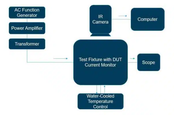
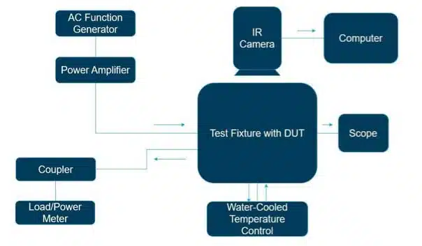
  2. Test Setup: Involves a combination of signal generators, power amplifiers, impedance matching components, and thermal monitoring apparatus.
  3. Capacitor Types: The study analyzes NP0, X7R, and Tantalum capacitors, each with unique ESR characteristics influencing ripple current tolerance.
  4. Data Collection & Analysis: Encompasses impedance characterization, progressive voltage application, and thermal monitoring to determine ripple current limits.
  5. Design Implications: Provides insights into optimizing power delivery and ensuring component reliability across various environments.

Extended Summary:

The increasing prevalence of embedded systems and the shift towards electrification underscore the growing importance of ripple current in electronic design. Ripple current, the AC component superimposed on a DC supply, affects the thermal performance and reliability of capacitors due to its relationship with ESR. This document details a comprehensive ripple current test designed to evaluate capacitor performance across diverse applications, from RF/microwave systems to automotive electronics.

The ripple current test setup is sophisticated, incorporating function generators, power amplifiers, impedance matching devices, and thermal imaging equipment to assess both unmounted and mounted device configurations. These setups are tailored to accommodate different ESR tiers and frequency ranges, extending up to 1 GHz for high-frequency applications.

Figure 1. Block diagram of the ripple current test apparatus for low frequency ranges up to 12 MHz.
Figure 2. Block diagram of the ripple current test apparatus for high frequency ranges up to 1 GHz.

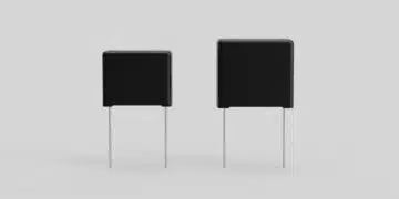
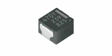
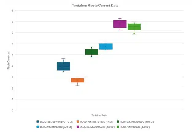
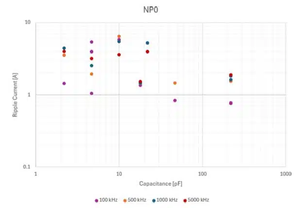
Three capacitor types—NP0, X7R MLCC capacitors, and Tantalum capacitors were studied. NP0 capacitors, known for minimal ESR and temperature stability, support high ripple currents, making them ideal for high-frequency applications. X7R capacitors offer stable performance over a broad temperature range and exhibit moderate ESR, suitable for general-purpose applications. Tantalum capacitors, with higher ESR, demonstrate self-healing properties and are robust under high ripple current conditions, beneficial for automotive applications.

Figure 3. Capacitance vs. ripple current data for X7R parts for 100 kHz, 500 kHz, 1000 kHz, and 5000 kHz frequencies.
Figure 5. Capacitance vs. ripple current data for tantalum parts for 100 kHz frequency at 45°C baseline temperature.
Figure 4. Capacitance vs. ripple current data for NP0 parts for 100 kHz, 500 kHz, 1000 kHz, and 5000 kHz frequencies.
Figure 6. Max voltage and current plots for a high capacitor value NP0 part with a 630V rating.

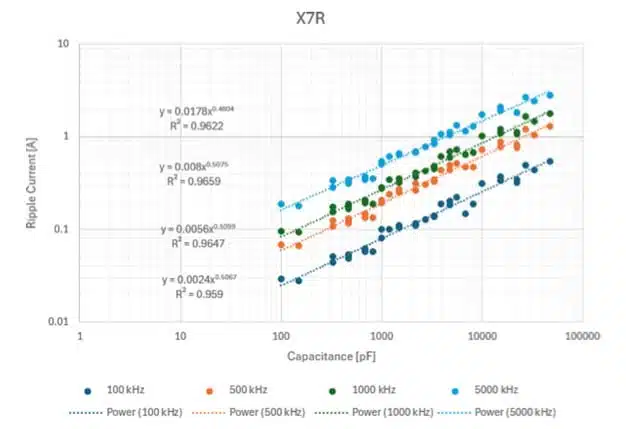
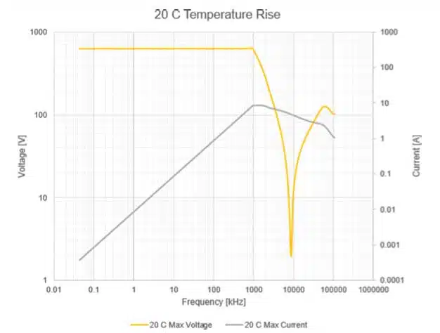
The data collection process involved impedance and ESR characterization using precision analyzers, followed by progressive voltage application to observe thermal responses. Data analysis revealed trends correlating capacitance, frequency, and ripple current tolerances. Notably, lower ESR corresponds with higher ripple current capabilities. The study identified the need for ongoing data collection to refine predictive models, particularly for NP0 and Tantalum capacitors.

Future modifications aim to enhance test setups for higher frequency data capture and minimize measurement discrepancies. Improved models will support design decisions in EV charging systems, power-efficient circuits, and high-frequency applications, ensuring component reliability and performance across diverse operational environments.

Conclusion:

Ripple current testing is vital for modern electronic design, providing critical insights into component behavior under dynamic conditions. By understanding the interplay between ripple current, ESR, and capacitance across various capacitor types, designers can optimize electronic systems for durability, efficiency, and reliability. Ongoing research and data refinement will continue to enhance these insights, supporting the development of robust, future-ready electronic solutions.

read the full paper:

KAVX-Ripple-Current-Increasingly-Relevant-TestDownload

Related

Source: KYOCERA AVX

Recent Posts

MLCC Manufacturers Consider Price Increase as AI Demand Outpaces Supply

18.2.2026
17

YAGEO Extends Antenna Portfolio with Wi‑Fi 6E/7 and Tri‑band GNSS Solutions

17.2.2026
5

SCHURTER Introduces 2410 SMD Fuse for Robust AC/DC Protection

17.2.2026
3

TDK Releases High Temp 175C Automotive NTC thermistors

17.2.2026
2

TU Wien Sets New Benchmark in Superconducting Vacuum Gap nanoCapacitors

16.2.2026
10

2026 Power Magnetics Design Trends: Flyback, DAB and Planar

13.2.2026
27

Vishay Releases Sulfur‑Resistant Chip Resistors

12.2.2026
9

Würth Elektronik Introduces Lead-Free SMT Spacers

11.2.2026
21

Schurter Releases EKO HV Fuses up to 1000 VDC, 1100 A

11.2.2026
6

Upcoming Events

Feb 24
16:00 - 17:00 CET

Mastering Galvanic Isolation: Ensuring Safety in Power Electronics

Mar 3
16:00 - 17:00 CET

Cybersecurity at the Eleventh Hour – from RED to CRA – Information and Discussion

Mar 21
All day

PSMA Capacitor Workshop 2026

View Calendar

Popular Posts

  • Buck Converter Design and Calculation

    0 shares
    Share 0 Tweet 0
  • Boost Converter Design and Calculation

    0 shares
    Share 0 Tweet 0
  • LLC Resonant Converter Design and Calculation

    0 shares
    Share 0 Tweet 0
  • Flyback Converter Design and Calculation

    0 shares
    Share 0 Tweet 0
  • Ripple Current and its Effects on the Performance of Capacitors

    3 shares
    Share 3 Tweet 0
  • Dual Active Bridge (DAB) Topology

    0 shares
    Share 0 Tweet 0
  • What is a Dielectric Constant and DF of Plastic Materials?

    4 shares
    Share 4 Tweet 0
  • MLCC and Ceramic Capacitors

    0 shares
    Share 0 Tweet 0
  • 3-Phase EMI Filter Design, Simulation, Calculation and Test

    0 shares
    Share 0 Tweet 0
  • SEPIC Converter Design and Calculation

    0 shares
    Share 0 Tweet 0

Newsletter Subscription


Passive Components Blog

© EPCI - Leading Passive Components Educational and Information Site

  • Home
  • Privacy Policy
  • EPCI Membership & Advertisement
  • About

No Result
View All Result
  • Home
  • Knowledge Blog
  • PCNS

© EPCI - Leading Passive Components Educational and Information Site

This website uses cookies. By continuing to use this website you are giving consent to cookies being used. Visit our Privacy and Cookie Policy.
Go to mobile version