


This article shows some common and also not so known capacitor symbols with brief description.
Standards
There are two symbols standards used in USA/Japan (NEMA) style and IEC “new boxed” style used in Europe.
Primary standards
The primary electrotechnical symbol standards are: IEC 60617 (international) and ANSI Y32.2 / IEEE 315 (US/North America).
IEC 60617 is the main international electrotechnical symbol standard, and ANSI Y32.2 / IEEE 315 is the historic and still‑referenced US standard for electrical/electronic diagrams, including capacitors. ISO 14617 is a general graphical symbol library for diagrams, but for pure electrotechnical symbols ISO itself explicitly defers to IEC 60617 DB, which is the authoritative source for capacitor symbols and similar.
On regional usage (Europe vs US/Asia)
IEC symbols are predominantly used in Europe and many international designs, while ANSI/IEEE symbols remain common in North America; Japan and some Asian manufacturers mainly follow IEC‑aligned JIS symbols.
Key Takeaways
- The article describes various capacitor symbols along with their functions.
- There are more symbol standards: Europe (IEC “new”), US (IEEE “old”) or symbols used in Japan.
- Generic capacitors store energy and can connect in any direction, while polarized electrolytic capacitors have positive and negative terminals.
- Variable capacitors allow for adjustable capacitance, commonly used in tuning circuits.
- Specialized capacitors like temperature-dependent and voltage-dependent capacitors have unique characteristics and applications.
- The article also discusses unique designs such as differential, butterfly, and dual ganged capacitors for advanced circuit functionality.
Capacitor Symbols
Generic Capacitor
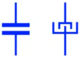
Capacitor is an electronic component that stores energy in its electric field. It is the symbol of a generic capacitor. It is a non-polar electrostatic capacitor having fixed capacitance value such as ceramic capacitors, silicon capacitors or film capacitors from the most common types. It can be connected in either direction. The second symbol represents an obsolete capacitor symbols used for non-polar capacitors.
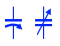
Polarized Electrolytic Capacitor

Such type of capacitors uses electrolyte as one of its electrode that is why they are polarized. The electrolytic capacitors such as aluminum capacitors, tantalum capacitors / niobium capacitors or supercapacitors have positive and negative terminals and the top of these symbols represent the positive terminals. A polarized capacitor must be connected in circuit accordingly, otherwise it may fail in its function. The first two symbols are used in Europe (IEC “new”) while the next two symbols in US (IEEE “old”) . The 5th symbol for capacitor is used in japan.
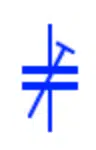
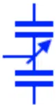
Variable Capacitor
This symbol represents a variable capacitance whose capacitance can be varied during normal operation. The capacitance is varied by increasing or decreasing the effective area between the plates that effects the capacitance of the capacitor. They are used in LC tuning circuits.
Trimmer Capacitor
It is also a variable capacitor whose capacitance is used to calibrate a circuit during manufacturing or troubleshooting a circuit. The capacitance of such capacitor is not normally changed by users during operation.
Bipolar Capacitor

They are also known as non polar electrolytic capacitor, usually aluminum electrolytic bipolar capacitors. It is made of two electrolytic capacitor in such design that they can be used in any polarity. They differ from generic ceramic non polar capacitor by having large capacitance.
Feed through Capacitor
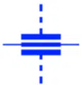
This type of capacitor is designed for DC power supply in RF systems. It supply the pure DC signal & also filters any RF component from it.
Voltage Dependent Capacitor

The capacitance of such capacitor depend on the applied voltage. Increasing or decreasing the supply voltages changes the size of the dielectric gap between the plates which increases the capacitance.
Temperature Dependent Capacitor
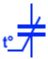
These capacitors capacitance depends on its surrounding temperature. The temperature increase or decrease may increase or decrease the capacitance of the capacitor. They are used in temperature sensing application.
Differential Capacitor

It is a variable capacitor with two operate stator and one common rotor. Moving the rotor increases the capacitance in one section & simultaneously decreases it in the other section. However the total capacitance remains the same.
Split Stator Capacitor

As the name suggest, such type of variable capacitor has two set of stators that are separated at 180° . A common shaft rotates the rotor that has the same vanes placed 180° apart. Such capacitors do not have the 90° limitation of a generic variable capacitor.
Dual Ganged Capacitor
It is the combination of two variable capacitor. The variable rotor of these both capacitors is controlled using a single shaft. Thus they provide variable capacitance in both capacitors by moving a single rotor.
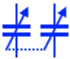
Butterfly Capacitor
Such type of variable capacitor has two separate stators opposite to each other mounted on the body of the capacitor. The rotor whose plates are also butterfly shaped, rotates between these two stators. The capacitance in such capacitor varies equally between either stator & rotor. They are used in symmetrically tuned circuits.
Tempatrimmer / Thermotrimmer
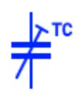
Tempatrimmer or also known as thermotrimmer is a small trimmer capacitor with a variable temperature coefficient. They are used in stabilizing the drifting VFos.
Regional and Historical Variants – Capacitors
- DIN 40900 (Germany – Obsolete)
The German DIN 40900 standard, later superseded by IEC 60617, used capacitor symbols closely aligned with modern IEC practice, with plate- or rectangle-based representations for fixed capacitors and added markings for polarity and adjustability. Older German schematics may therefore show IEC‑style plate symbols or simplified variants rather than distinct “national” capacitor icons. - AS 1102 (Australia – Obsolete)
The Australian AS 1102 standard has been replaced by adoption of IEC 60617 and related IEC graphical symbol standards. Historical Australian schematics can show minor variations in capacitor plate spacing, orientation, and polarity marking style, but the underlying meaning remains consistent with IEC conventions. - JIS (Japanese Industrial Standards)
For capacitors, Japanese JIS C 0617 was established by adapting IEC 60617, so modern JIS symbols generally follow IEC forms, with only partial changes in capacitor symbol details. Some older Japanese schematics, especially from periods of strong US influence, may use ANSI‑style capacitor symbols with simple parallel plates and the familiar curved‑plate polarized symbol.
Symbol Selection Guidelines
Choosing Between IEC and ANSI
- International projects: Use IEC 60617 capacitor symbols (rectangle/box style for non‑polarized, boxed symbol with explicit polarity marking for polarized types) for broad international compatibility.
- US‑based projects: ANSI/IEEE 315 capacitor symbols (two parallel plates for non‑polarized, straight/curved plates for polarized) remain common in North American industry and education.
- Consistency: Never mix IEC and ANSI capacitor symbol styles within a single schematic diagram, as this can confuse readers and automated tools.
- Documentation: Always specify the symbol standard used (for example “Symbols per IEC 60617” or “Symbols per IEEE 315”) in the drawing title block or notes.
Modern Trends
Current practice shows increasing adoption of IEC 60617‑style capacitor symbols globally, including in many CAD libraries, even for designs targeting traditionally ANSI‑dominated regions. Most modern EDA tools provide both IEC and ANSI capacitor symbol sets and allow users or libraries to define the default style per project or company standard.
Reference Designations and Value Notation
Regardless of the graphical symbol standard, capacitor designations follow broadly harmonized conventions:
- Reference designator: Capacitor references begin with C followed by a sequential number (C1, C2, C3, etc.).
- Value notation: Capacitance is expressed in farads (F), most often using decimal-scaled units such as nF, µF, or pF depending on magnitude.
- Tolerance: Commonly indicated as a percentage (for example ±5%, ±10%, ±20%) or with an IEC tolerance code when relevant.
- Voltage rating: Specified in volts (for example 16 V, 50 V, 450 V) and considered critical for safety and reliability, especially for polarized capacitors.
- Polarity: For polarized capacitors (electrolytic, tantalum), the positive terminal is usually indicated by a “+” mark or distinct plate style in the symbol and must match the PCB footprint and BOM.
Example Reference Designation
C15
4.7 µF ±10%
25 V.
Standards Overview for Capacitors
| Standard | Region | Status | Capacitor symbol style / notes |
|---|---|---|---|
| IEC 60617 | International | Active | Plate/rectangle‑based symbols, explicit variants for polarized, adjustable, and special types. |
| ANSI Y32.2 / IEEE 315 | United States | Active (not frequently updated) | Parallel‑plate and curved‑plate capacitor symbols; multiple styles defined for variable parts. |
| ISO 14617 | International | Active | General graphical symbol framework aligned with IEC‑style passive component symbols. |
| DIN 40900 | Germany | Obsolete | Historically IEC‑like capacitor symbols; superseded by IEC 60617‑based standards. |
| AS 1102 | Australia | Obsolete | Replaced by IEC adoption; minor historical variations only. |
| JIS C 0617 | Japan | Active | Adapts IEC 60617; minor local differences for capacitor circuit symbols. |
Global capacitor symbol standards summary
Understanding capacitor symbol variations across IEC, ANSI/IEEE, and related national standards is important for clear communication in international electronics design. While the functional idea is consistent—fixed versus variable, polarized versus non‑polarized—the graphical style differs mainly between the IEC box/rectangle convention and the ANSI plate‑based forms, so the most important practices are choosing one style per project, maintaining internal consistency, and documenting the governing standard.
Frequently Asked Questions about Capacitor Symbols
The generic capacitor symbol represents a non-polar capacitor with a fixed capacitance value. It can be connected in either direction and is commonly used in circuit diagrams.
Polarized electrolytic capacitors are marked with positive and negative terminals. The symbol indicates polarity, and incorrect connection can cause the capacitor to fail or explode.
A variable capacitor allows capacitance adjustment during normal operation, often used in tuning circuits. A trimmer capacitor is adjusted only during manufacturing or calibration and not by end users.
Feed-through capacitors filter RF noise in DC power lines, while temperature-dependent capacitors change capacitance with temperature, making them useful in sensing applications.