


Vishay Intertechnology application note on the resistor pulse load characterisation. The article compares different resistor manufacturing technologies from the point of their capability to handle high power pulse load. Carbon film MELF has been identified as the champion – you can read more about the reasons and technology backgrounds.
INTRODUCTION
Many electronic circuits are exposed to high pulse loads. In some applications these occur regularly, such as in pulse width modulated (PWM) devices. In others pulses are incidental, but also inevitable — resulting from electromagnetic interference signals (EMI). Unfortunately, due to the increasing miniaturization or intrinsic limitations of electronic components, their pulse load capability is often insufficient to withstand these pulse loads and they require protection.
Whether pulse loads are regular or incidental, pulse-proof resistors are needed, and MELF resistors are especially well suited to this application due to their excellent pulse load capability — a prominent feature linked to their unique cylindrical design. In addition to standard metal film technology, MELF resistors are available with carbon film, which further enhances their pulse load capability. The largest case size (0207) carbon film MELF not only provides the highest pulse load capability of MELF resistors, but of all SMD film resistors, thus making it the optimum choice for high-pulse-load applications.
This article will help designers in selecting the optimum resistor for protection by identifying the pulse properties — power, duration, and shape — that need to be considered. For this, the effects of pulses on resistors and the factors determining their pulse load capability are explored, and the resulting advantages of carbon film MELF resistors are illustrated.
APPLICATION REQUIREMENTS AND BENEFITS
a) Pulse Width Modulation Devices PWM Devices
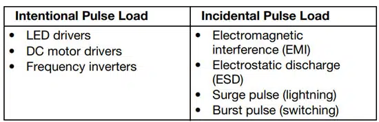
A very common application is PWM, which is employed in various automotive, industrial, and alternative energy applications, including LED drivers for luminosity control; frequency inverters that match the output voltage and frequency to 3-phase AC drives; and DC motor drivers for speed adjustment.
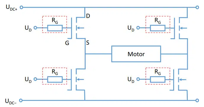
A DC motor driver circuit is illustrated in Fig. 1. Here, PWM is realized by frequent switching of four MOSFETs arranged in an H-bridge. The motor voltage is then determined by the switching frequency as well as the switching speed, which is controlled by the gate resistors. Although quick switching is favoured because of low switching losses, it can induce undesired EMI signals, or ringing of the circuit. As the gate resistor is exposed to the PWM pulses, it must have a sufficient pulse load capability.
b) Incidental Pulse Loads
Pulse-load-sensitive elements in electronic circuits can be protected by the integration of dedicated sub-circuits. These typically work as bypass or load sinks and feature different components ranging from smoothing capacitors to voltage-suppressing diodes. Their common element, however, is the pulse-resistant resistor, inserted to absorb the pulse power or lower the pulse voltage over the pulse-sensitive component to a non-critical level. Sources of incidental pulses are grid- or field-bound EMI signals, including broadband burst pulses induced by switching actions, surge pulses caused by lightning, as well as ESD.
Protection against burst pulses or ringing effects caused by field-bound EMI signals in electrical systems with inductive or capacitive loads is provided by RC-snubber circuits. These have an attenuating effect on the voltage rise across the switching device and dissipate the energy of the resonant circuit.
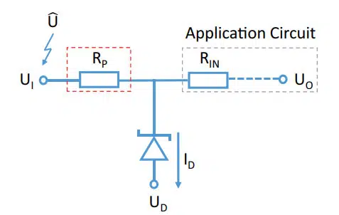
Nearly every electronic application is potentially exposed directly or indirectly to lightning strikes that result in a surge pulse load on the electronic circuit. Surge pulses have high energy and can reach voltages of several thousand volts. Protection of sensitive components against them can be realized using the circuit shown in Fig. 2. For this, a transient voltage suppression (TVS) diode is employed to divert the surge pulse load from the application circuit and balance its voltage at an acceptable level. Here, the function of the resistor is to regulate the diode current.
The high-pulse-load resistors used in the above applications have to be selected thoroughly. For this, general application requirements — such as the resistor’s tolerance and temperature coefficient — have to be considered. Finally, the key factor is its pulse load capability, which has to be sufficient for the highest anticipated pulse load.
Because of this complexity, we will give guidance on the selection of suitable resistors by estimating the pulse load for two examples:
- A gate resistor in a motor driver (Fig. 1)
- A protective resistor in a surge pulse protection circuit (Fig. 2)
Before we turn to these examples in Section 5, we will address the factors determining the pulse load capabilities of resistors of different technologies.
EFFECTS OF PULSE LOAD ON THE RESISTOR
The pulse load capability of a resistor is determined by its ability to dissipate the pulse power. It depends on various resistor properties, particularly its geometry, the utilized trimming pattern, and the resistive film material.
Thermal Energy and Pulse Duration
In the resistive layer the pulse power is converted into heat by electrical loss. The heat generated depends on the pulse energy and causes an increase in the resistor’s temperature.
For very brief pulses, the created heat remains in the resistive film. If the latter is homogeneous, the heat is distributed evenly. However, when the film is overheated the resistor is damaged. With increasing pulse duration, the heat is dissipated depending on the heat transfer capabilities of the resistor. Finally, the load may be considered continuous and the permissible pulse load approaches the rated dissipation.
Furthermore, repetitive pulses, for which complete cooling of the resistive film between them is prevented, lead to a cumulative temperature increase. An effect that renders a resistor’s pulse load capability for continuous pulse trains lower than that of single pulses.
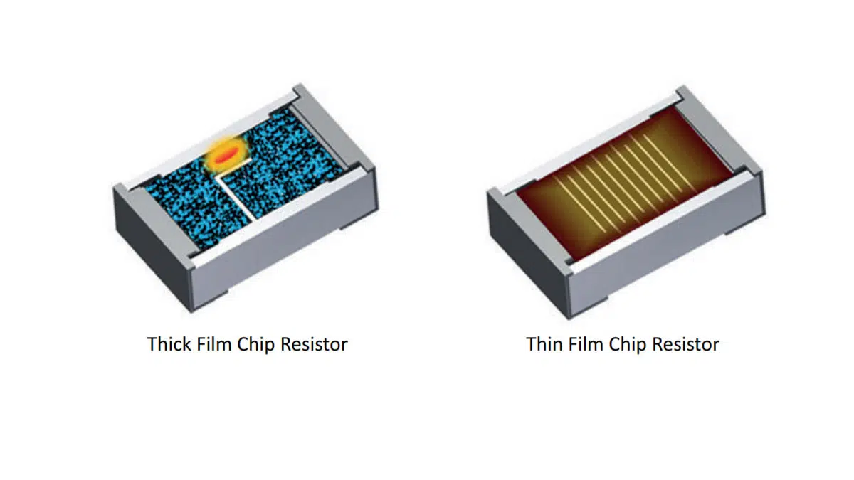
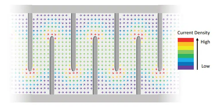
In fact, heat is only created where current actually flows. Typically, for fine adjustment of the resistance, a trimming pattern is cut into the film. This pattern defines the current path and thereby reduces the effectively utilized resistive area. Schematic patterns and the resulting effective resistive areas of SMD film resistors are shown in Fig. 3.
Effective Resistive Film Area and Trimming Pattern
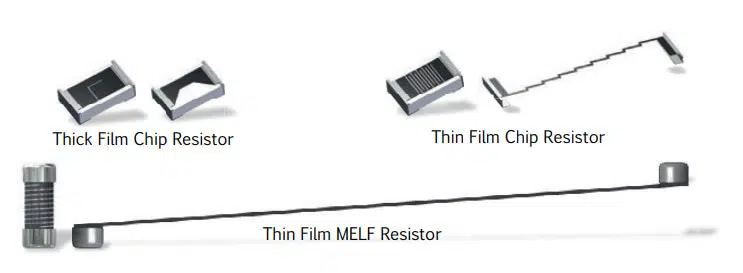
Thick Film Chip
Let’s first consider a thick film chip resistor, which exhibits a simple L-cut trimming pattern. This pattern reduces the effective area and creates a local hotspot, as illustrated in Fig. 4.
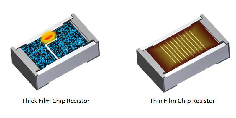
Thin Film Chip
In contrast, the elaborate thin film chip resistor meander cut trimming pattern facilitates a homogeneous current and heat distribution in the film. In addition, the effectively used film area is distinctively increased. For this pattern, however, a limiting factor is that current flow turning points occur, where the current density is locally increased, as is illustrated in Fig. 5.
There again, local overheating can occur, leading in the worst case to evaporation of the resistive film material and subsequent opening of the resistor.
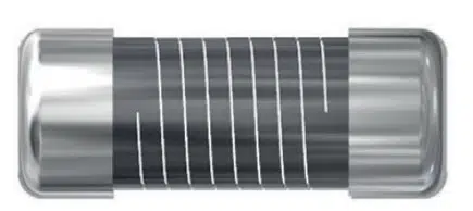
Thin Film MELF
A uniform trimming pattern and a large effective resistive area is realized by the thin film MELF resistor design. Its cylindrical shape enables a turning-point-free helical trimming pattern, as shown in Fig. 6. In addition, the effective film area is increased by a factor of p, making it by far the largest of the SMD film resistors in comparable case sizes.
Resistive Film Material
Since the effects mentioned above all result in a film temperature increase, the pulse load capability of a resistor is strongly related to the chosen film material, its resistivity and TCR. In thick film technology, mixed metal / metal oxide / glass pastes are used that are very sensitive to thermal stress, and thus further contribute to the thick film resistor’s limited pulse load capability. In contrast, the uniform metal alloy films commonly used in thin film technology exhibit a much higher pulse load capability. However, none of them has a thermal stability comparable to that of carbon, which has the highest sublimation point (~ 3900 K) of all elements. This distinct feature allows the carbon film MELF resistor to best withstand the thermal effects created by high pulse loads.
Besides resistor geometry and film material, other production-related factors — such as a clean trimming cut, good adhesion between the film and ceramic substrate to facilitate thermal conduction, or thermal properties of other resistor materials such as the ceramic substrate — may affect the resistor’s pulse load capability to a large degree. High-quality manufacturing and well-matched composition of the resistor’s elements are therefore of high importance.
In summary, the most significant factors determining the pulse load capability of SMD resistors are the effective area of the resistive layer, a trimming pattern that supports homogeneous current flow, and a resistive film material of high thermal stability. In the carbon film MELF resistor, all of them are adapted to facilitate optimum pulse load capability.
PULSE LOAD CAPABILITY OF SMD FILM RESISTORS
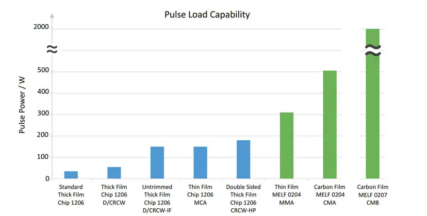
The destructive pulse load limits of a standard thick film chip resistor, together with advanced thick film chip, thin film chip, and thin film MELF resistors of comparable case sizes (1206 / 0204), and the 0207 case size carbon film MELF, are given in Fig. 7.
The destructive pulse load limit of the standard thick film chip resistor is rather low at 35 W. This is a direct consequence of the technological drawbacks regarding pulse load capability described above: small effective area and hot-spot-creating trimming pattern. In contrast, for the advanced thick film chip resistor the destructive limit is more than 50 % higher. Optimized thick film designs omit trimming or double the resistive area by applying a trimmed film on the resistor’s top and bottom sides. In both cases the destructive pulse load limit is significantly improved. For the latter design it even exceeds the thin film chip resistor’s limit, whose pulse load capability, compared to standard thick film technology, benefits greatly from an advanced trimming pattern, increased effective area, and better thermal stability of the homogeneous film material. Nevertheless, the advantages of the cylindrical MELF design are clearly evident in another increase of the destructive limit by 70 % for the thin film MELF resistor. Of all SMD devices of the same case size, however, it is the carbon film MELF resistor that withstands the highest pulse load of » 500 W.
Considering the largest case size 0207 available for carbon film MELFs, which is of course accompanied by a similarly enlarged effective film area, its destructive pulse load limit is increased to 2 kW — more than an order of magnitude larger than the thick film chip resistor’s limit. This unparalleled high pulse load capability makes the carbon film MELF the SMD champion for high-pulse-load applications.
DIMENSIONING OF RESISTORS IN PULSE LOAD APPLICATIONS & SUMMARY
Finally, we will illustrate the selection of suitable resistors for high-pulse-load applications using the two examples presented in Section 2: the gate driver circuit in a motor driver application and the surge pulse protection.
a) PWM Devices: Gate Driver Circuit
In this example we will deal with the motor driver shown in Fig. 1. The motor speed is adjusted by PWM, realized by the frequent switching of MOSFETs. To control the MOSFETs’ switching speed, a gate resistor is used. Since the resistor is likewise exposed to pulses, it must feature a high pulse load capability.
Although different gate resistors are often employed to adjust on / off switching speed separately, here for simplicity we consider just one (RG).
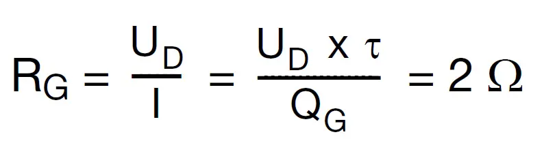
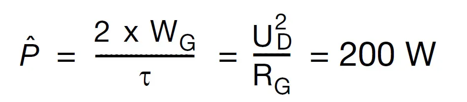
Switching of the MOSFET requires recharging of its gate capacitance with a gate charge QG, which is achieved by the application of a driving voltage UD. This process, which follows an exponential behavior described by the time constant t, determines the switching speed. It is biased by the (dis)charging current i = dQG / dt, which in turn is controlled by the gate resistor. Thus, the gate resistance is defined by the desired switching duration. In our example we consider a motor that runs at a frequency of f = 17 kHz. A MOSFET of gate charge QG = 2 μC is chosen, and driven by UD = 20 V. The duration of the exponential switching pulse shall be t = 200 ns.
Selection of Components
- To define the switching duration, the resistance has to be set to
- The power load on the resistor has to be estimated. The PWM creates a continuous pulse train. Thus the resistor is exposed to continuous pulses as well as an average power
- The average power is determined by the energy content of the gate capacitor released in every on / off switching process, and the switching frequency:
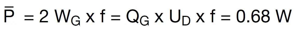
It is equivalent to the power load on a resistor under continuous operation. In datasheets, the permissible limit is specified as the rated dissipation P70. A comparison of the P70 of the SMD resistors considered above shows that only the largest case size (0207) metal and carbon film MELF resistors, whose rated dissipation is 1 W, are able to withstand this average power.
- The power per pulse is determined by the gate capacitor’s energy content WG as well as the switching pulse length t:
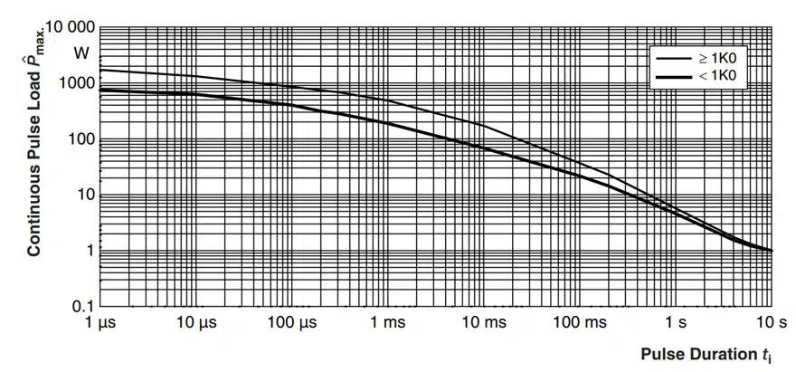
The pulse load capability for continuous pulse trains is specified in the datasheet of the resistor. It can be found in the continuous pulse diagram, which is shown for the carbon film MELF resistor in Fig. 8.
In this diagram, rectangular pulses are considered. Therefore, to allow comparison, we have to convert our exponential pulse to a rectangular pulse of equivalent energy content, resulting in a change of pulse length according to tr = t / 2. Thus, in the pulse load diagram we have to compare with a pulse duration of tr = 100 ns. Verifying the specified permissible pulse load reveals that the carbon film MELF resistor fulfills all requirements.
The gate resistor used in this motor driver application to adjust the MOSFETs’ switching speed is continuously exposed to pulses. The selected resistor therefore must not only meet the pulse load requirements, but also withstand the resulting average power. Again, due to its outstanding pulse load capability, only the carbon film MELF resistor is found suitable for this application. Since its pulse load capability is much higher than necessary, it allows for MOSFETs of larger gate charge or shifting to shorter switching times.
b) Incidental Pulse Loads: Surge Pulse Protection
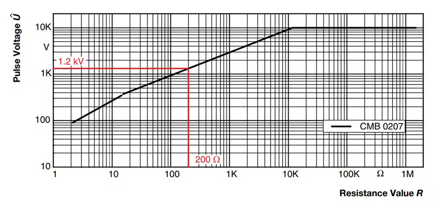
In this example (see Fig. 2) we consider a 24 V application with input resistance of RIN = 10 kW. The application is also assumed to be tolerant against voltage variations of up to 38 V. However, it has to be protected against any surge pulse of a larger voltage. Here this is achieved by diverting the pulse load via a TVS diode. For our estimates, we assume that we want to protect the application against a surge pulse of .
To handle board space limitations, the TVS diode should be as small as possible. This, however, limits its peak pulse power capability. Therefor a protective resistor is required to limit the diode current. These components have to be selected such that the input voltage of the application circuit is limited to UO = 38 V and the permissible power / voltage load on both components is not exceeded.
Selection of Components
- The resistance RP has to be balanced so that it limits the diode current appropriately, but also does not affect the application circuit under normal conditions. As it represents a voltage divider together with the input resistance, it has to be chosen much smaller, e.g. RP = 0.02 x RIN = 200 W.
- The peak diode current under surge conditions is then limited by the resistor, neglecting the much smaller diode voltage.
- The diode is selected according to the application’s specifications:
Reverse clamping voltage of about 38 V, to limit UO accordingly.
Breakthrough voltage slightly above 24 V, so that it is not conductive under normal conditions.
Peak pulse power capability larger than the maximum peak power load on the diode in this application. - Finally, the 200 W resistor must be able to withstand the surge pulse of 1 kV. This information is found in the 1.2 / 50 pulse diagram of the resistor’s datasheet. A corresponding diagram for the carbon film MELF resistor is shown in Fig. 9.
A comparison of permissible pulse voltages for 1.2 / 50 pulses for resistors of different technologies shows that only the carbon film MELF resistor exhibits a suitable limit of = 1.2 kV for this resistance value.
SUMMARY
The high peak power in pulsed and pulse protective applications requires SMD resistors of sufficient high pulse load capability. Failures of SMD resistors under pulse load are induced by the temporary strong heat generation in the device. Advanced carbon film MELF resistors have been specifically designed to combine the most important characteristics for high pulse load capability:
- The proven pulse-resistant cylindrical design, offering the largest effective resistive film area
- Helical trimming pattern, avoiding locally enhanced current densities
- The carbon film material, with its unrivaled thermal stability
In the largest case size available — the 0207 — the carbon film MELF resistor is the SMD champion in pulse load capability. Its performance is more than an order of magnitude better than comparable resistors of its class.


