Passive Components Blog
No Result
View All Result
  • Home
  • NewsFilter
    • All
    • Aerospace & Defence
    • Antenna
    • Applications
    • Automotive
    • Capacitors
    • Circuit Protection Devices
    • electro-mechanical news
    • Filters
    • Fuses
    • Inductors
    • Industrial
    • Integrated Passives
    • inter-connect news
    • Market & Supply Chain
    • Market Insights
    • Medical
    • Modelling and Simulation
    • New Materials & Supply
    • New Technologies
    • Non-linear Passives
    • Oscillators
    • Passive Sensors News
    • Resistors
    • RF & Microwave
    • Telecommunication
    • Weekly Digest

    Transformer Safety IEC 61558 Standard

    ESR of Capacitors, Measurements and Applications

    Murata Christophe Pottier Appointed President of EPCIA

    3-Phase EMI Filter Design, Simulation, Calculation and Test

    YAGEO Unveils Compact 2.4 GHz SMD Antenna

    KYOCERA AVX Releases Antenna for Iridium Satellite IoT Applications

    Molex Releases Industry-First Quad-Row Board-to-Board Connectors with EMI Shields

    Image credit: Samtec

    How to Match the Right Connector with Protocol Requirements

    Smoltek CNF-MIM Capacitors Pass 1,000h Reliability Test

    Trending Tags

    • Ripple Current
    • RF
    • Leakage Current
    • Tantalum vs Ceramic
    • Snubber
    • Low ESR
    • Feedthrough
    • Derating
    • Dielectric Constant
    • New Products
    • Market Reports
  • VideoFilter
    • All
    • Antenna videos
    • Capacitor videos
    • Circuit Protection Video
    • Filter videos
    • Fuse videos
    • Inductor videos
    • Inter-Connect Video
    • Non-linear passives videos
    • Oscillator videos
    • Passive sensors videos
    • Resistor videos

    Transformer Safety IEC 61558 Standard

    3-Phase EMI Filter Design, Simulation, Calculation and Test

    Transformer Design Optimization for Power Electronics Applications

    Common Mode Chokes Selection for RF Circuits in Next-Generation Communication Systems

    Capacitor Self-balancing in a Flying-Capacitor Buck Converter

    How to Select Ferrite Bead for Filtering in Buck Boost Converter

    Power Inductors Future: Minimal Losses and Compact Designs

    Percolation Phenomenon: Degradation of Molded Power Inductors in DC/DC Converters

    Connector PCB Design Challenges

    Trending Tags

    • Capacitors explained
    • Inductors explained
    • Resistors explained
    • Filters explained
    • Application Video Guidelines
    • EMC
    • New Products
    • Ripple Current
    • Simulation
    • Tantalum vs Ceramic
  • Knowledge Blog
  • Suppliers
    • Who is Who
  • PCNS
    • PCNS 2025
    • PCNS 2023
    • PCNS 2021
    • PCNS 2019
    • PCNS 2017
  • Events
No Result
View All Result
Passive Components Blog
No Result
View All Result

Clarifying MIL-STD-461 and EMI Filter Misconceptions

8.1.2020
Reading Time: 3 mins read
A A

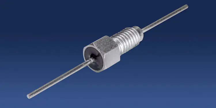
Some filter manufacturers may quote MIL-STD-461 in their literature, however this equipment specification that can’t be applied directly to filters. Knowles Precision Devices blog provides clarity on the standard clears up some common misconceptions.

The US MIL-STD-461 specification manages electromagnetic interference emissions by setting limits on the levels that can be emitted from electrical equipment. This specification also sets regulation to control equipment susceptibility to external noise sources and establishes guidelines for properly measuring the relevant equipment features.

RelatedPosts

Transformer Safety IEC 61558 Standard

ESR of Capacitors, Measurements and Applications

Murata Christophe Pottier Appointed President of EPCIA

For background, a piece of electrical equipment behaves as a “source” that generates EMI; EMI, transmitted by conduction and radiation, could be incident upon a receiver (for instance, another piece of electrical equipment or a test fixture). The level of the electromagnetic signature for the conducted emissions is determined by the characteristics of the receiver. For example, a switched-mode power supply (SMPS) may be “noisy” and filament lights may be “quiet.”

If emissions from the equipment exceed the limits set by MIL-STD-461, then they need to be attenuated using an EMI filter. In order to meet requirements, the filter must suppress emissions to a low enough level for the equipment to claim compliance across the frequency spectrum.

The electromagnetic signature of the equipment determines the EMI filter performance requirements, and the filter manufacturer can only get that information from the equipment manufacturer. From there, the claim for compliance can normally be verified by test and measurement. That said, no filter manufacturer can claim that their filters “meet” MIL-STD-461. MIL-STD-461 is an equipment specification that cannot be applied directly to filters.

All filter manufacturers catalogue their filter performance as insertion loss in a reference impedance system (typically 50Ω). The filter manufacturer does not know the level of emissions associated with a specific piece of equipment, nor the real-world terminating impedances as presented to the filter. The published filter insertion loss performance at, or across, a particular frequency range will not necessarily represent the equivalent attenuation of equipment emissions in practice. The equipment manufacturer will need to conduct their own tests to determine whether the part is suitable and the filtered equipment meets the requirements of MIL-STD-461.

A situation might arise where the proposed filter is “above specification” requirement, and the equipment easily conforms to MIL-STD-461. In contrast, equipment may be so electromagnetically noisy that a proposed filter would automatically fail to support the equipment in meeting MIL-STD-461 specifications. There is no guarantee that incorporating a particular filter into a piece of equipment will enable it to comply with MIL-STD-461 emissions limits.

Some filter manufacturers may quote MIL-STD-461 in their literature; however, no filter supplier can properly quote it. At Knowles Precision Devices, if we receive a filter inquiry that refers to MIL-STD-461, we ask exactly what level of attenuation you require. We can suggest part numbers based on that detail, but ultimately you will need to test parts to determine if they are suitable.

featured image source: Knowles Precision Devices

Related

Source: Knowles Precision Devices

Recent Posts

Transformer Safety IEC 61558 Standard

7.11.2025
1

ESR of Capacitors, Measurements and Applications

7.11.2025
10

3-Phase EMI Filter Design, Simulation, Calculation and Test

6.11.2025
23

YAGEO Unveils Compact 2.4 GHz SMD Antenna

6.11.2025
6

KYOCERA AVX Releases Antenna for Iridium Satellite IoT Applications

6.11.2025
8
Image credit: Samtec

How to Match the Right Connector with Protocol Requirements

6.11.2025
12

Transformer Design Optimization for Power Electronics Applications

4.11.2025
21

Microhardness — the Hidden Key to Understanding MnOx Cathode Quality in Tantalum Capacitors

3.11.2025
23

Lightweight Model for MLCC Appearance Defect Detection

3.11.2025
25

Smiths Interconnect Extends Space-Qualified, High-Reliability Fixed Chip Attenuators 

30.10.2025
10

Upcoming Events

Nov 11
17:00 - 18:00 CET

Industrial Applications Demand More from Interconnects in Next-Gen Designs

Nov 12
11:00 - 12:00 CET

PCB Design: Impedance is for everyone!

Nov 12
November 12 @ 12:00 - November 13 @ 14:15 EST

Microelectronic Packaging Failure Modes and Analysis

View Calendar

Popular Posts

  • Buck Converter Design and Calculation

    0 shares
    Share 0 Tweet 0
  • Boost Converter Design and Calculation

    0 shares
    Share 0 Tweet 0
  • LLC Resonant Converter Design and Calculation

    0 shares
    Share 0 Tweet 0
  • Flyback Converter Design and Calculation

    0 shares
    Share 0 Tweet 0
  • Ripple Current and its Effects on the Performance of Capacitors

    3 shares
    Share 3 Tweet 0
  • MLCC and Ceramic Capacitors

    0 shares
    Share 0 Tweet 0
  • Dual Active Bridge (DAB) Topology

    0 shares
    Share 0 Tweet 0
  • What is a Dielectric Constant and DF of Plastic Materials?

    4 shares
    Share 4 Tweet 0
  • SEPIC Converter Design and Calculation

    0 shares
    Share 0 Tweet 0
  • Flying Capacitors

    0 shares
    Share 0 Tweet 0

Newsletter Subscription


Passive Components Blog

© EPCI - Leading Passive Components Educational and Information Site

  • Home
  • Privacy Policy
  • EPCI Membership & Advertisement
  • About

No Result
View All Result
  • Home
  • Knowledge Blog
  • PCNS

© EPCI - Leading Passive Components Educational and Information Site

This website uses cookies. By continuing to use this website you are giving consent to cookies being used. Visit our Privacy and Cookie Policy.
Go to mobile version