The majority of connector contacts are manufactured from copper alloys due to the combination of high electrical conductivity and good mechanical strength and formability characteristics. This section will provide an overview of copper alloy metallurgy to explain how those characteristics are obtained and used in the manufacture of connector contacts.
Copper Alloy Metallurgy
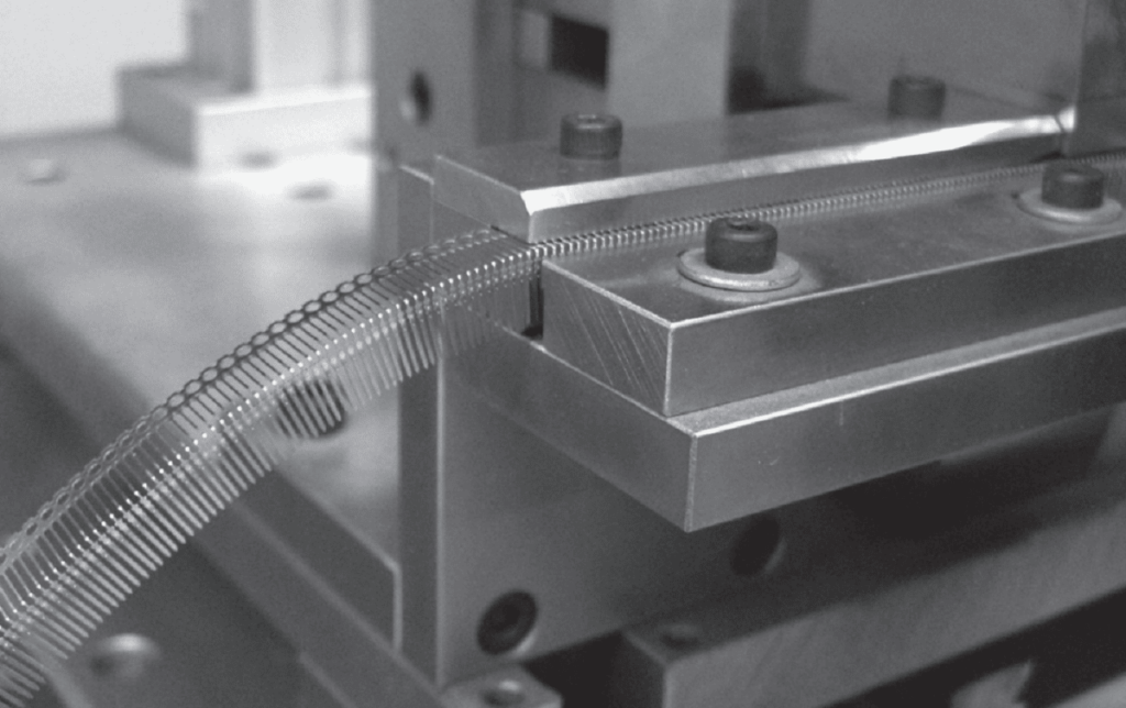
With the exception of silver, copper has the highest electrical conductivity of any metal. Mechanically, copper has moderate strength and good formability. Formability refers to the ability to take a metal and bend or form it into various contours, such as the connector receptacle contacts shown in Figure 1.25, without cracking. By adding other elements into the copper matrix, alloying, the mechanical characteristics of copper can be improved significantly without unacceptable loss in formability. The changes in mechanical performance characteristics depend on the alloying element, e.g. tin, zinc or beryllium, and the amount of the alloying element added to the copper. Most copper alloys used in connectors are lightly alloyed with alloy contents of less than ten percent. Cartridge brass, arguably the most common contact material due to heavy use in white goods and industrial applications, is the major alloy with a higher alloy content, being nominally 70 percent copper and 30 percent zinc.
The improvements in mechanical performance, however, are accompanied by a significant decrease in electrical conductivity. A common benchmark for the electrical conductivity of copper alloys uses the International Annealed Copper Standard, IACS, as a reference. Against this standard, copper has a conductivity of 102 percent IACS while phosphor bronze, copper/5%tin has an IACS conductivity of 20 percent, a significant decrease. Even at these conductivity levels, however, copper alloys are still highly conductive. For comparison the conductivities of aluminum and nickel, in IACS values, are 61% and 16% respectively.
Consider now some of the details of alloying of copper with respect to electrical conductivity and mechanical performance. The discussion begins with electrical conductivity effects.
Alloying and Electrical Conductivity
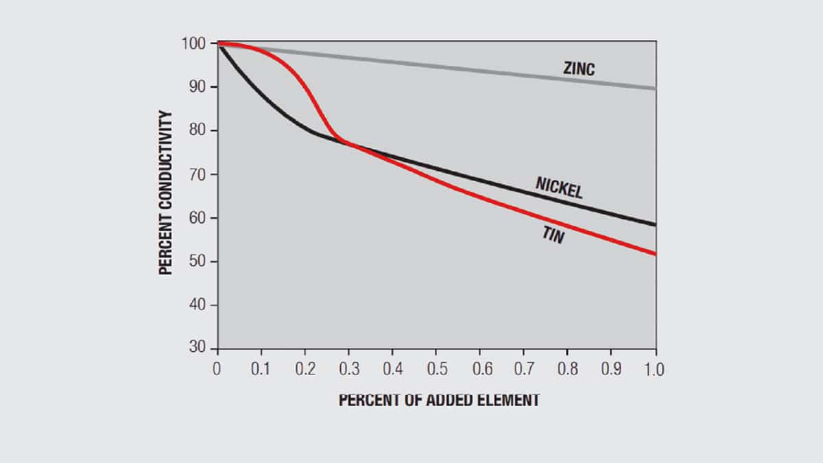
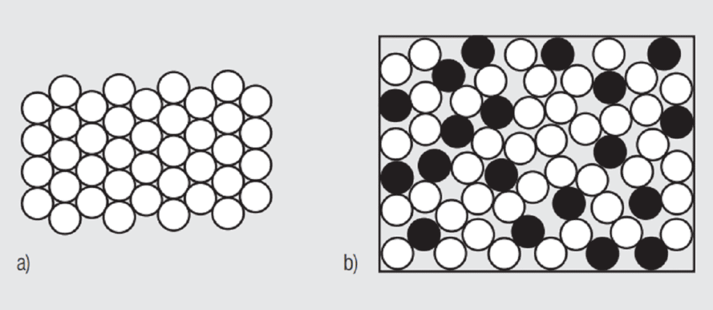
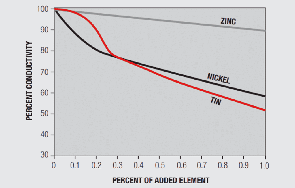
A simplistic, but basically accurate, explanation for the high conductivity of metals is that they contain free electrons, electrons that are not tied up in the inner shells of the atomic structure. When an electric field is applied to a metal, these free electrons are accelerated by the field and result in current flow. While these free electrons are free from individual atoms, they are surrounded by other atom shells which can impede the flow of the free electrons, that is, scatter the free electrons and introduce resistance into the system. In pure copper, all the atoms are on fixed positions in a close packed attice, as schematically illustrated in Figure 1.26a, and this fixed structure introduces a characteristic resistance, the resistance of copper. If other elements are added to the copper they will have different characteristics, size and electronic structure, so they will distort the lattice, as shown in Figure 1.26b, increasing the scattering of the free electrons and, thus, the electrical resistance. The degree of increased scattering depends on the alloying elements and the amount of alloying additions. Figure 1.27 shows the effect of small additions of zinc, tin and nickel to copper.
Alloying and Mechanical Properties
Before discussing the effects of alloying on mechanical properties a discussion of pure metal mechanical properties is in order. Figure 1.28 contains a stress-strain curve for a metal under a tensile, uniaxial, load. The important parameters in the figure are:
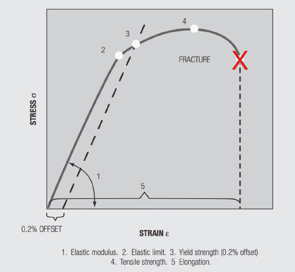
Elastic (Young’s) Modulus, E, is the slope of the stress versus strain curve in the initial stages of loading. Elastic means that if the load is applied and removed the sample will return to its original length. The elastic modulus depends on the material and, in copper alloys, is not significantly affected by alloying. The range in E across the commonly used copper alloys is between 16 to 20.106 psi. In Chapter II/2.2 Contact springs the elastic modulus will be related to the spring rate, the force versus deflection, of a cantilever beam, an important connector design parameter.
Yield strength, is the stress at which a given permanent set, a permanent increase in the length of the sample when the load is removed, is introduced into the sample. For copper alloys the yield strength is generally taken at 0.2 percent offset, that is, the stress at which the length of the sample has increased by 0.2 percent. The value is obtained from the stress-strain curve by drawing a line parallel to the Elastic modulus from the 0.2 percent elongation point on the strain axis. Permanent set is due to plastic, non-reversible, deformation of the sample. Plastic deformation begins when the applied stress is sufficient to cause individual atoms to be displaced from their equilibrium positions in the metal lattice on an atomic scale distorting the local lattice structure. As the distortion increases under increasing stress, groups and planes of atoms, called dislocations, move relative to each other, generally along close packed planes resulting in the macro distortion of permanent set. The introduction of such defects into the lattice makes the lattice more resistant to additional deformation, strengthening the lattice. This strengthening is referred to as “work hardening” because the “work”, the deformation, “hardens”, strengthens, the lattice. All metals, pure and alloys work harden. There is an additional hardening mechanism relevant to both pure metals and alloys, grain size hardening. The copper and copper alloys used in connectors are polycrystalline. A cross-section through a contact would show numerous grains separated by grain boundaries. Figure 1.29 shows two grain size reference photographs. The number with the figure indicates the “average” grain size in the photo. The hardening mechanism of grain size actually comes about due to the grain boundaries. The orientations of the grains on either side of the boundary will be different, so the close packed planes will not be continuous and the dislocation motion will be stopped or inhibited, thus, the material will be strengthened. Clearly the relative amount of grain boundary compared to grain is higher as grain size decreases so the hardening effect is stronger. There are two other hardening mechanisms that come into play due to alloying. These mechanisms will be discussed when the discussion of the stress-strain curve is completed.

The final property of interest in the stress-strain curve is elongation, the increase in the length of the sample under load. The importance of elongation is its relationship to ductility, which, in turn, is a measure of the ability to stamp and form the material without unacceptable damage, i.e. cracking in the bend zones. Yield strength and elongation are inversely related, which is to be expected.
Alloy Hardening Mechanisms
Alloying directly affects yield strength in two ways. First, as noted in the discussion of electrical conductivity, alloying elements distort the lattice structure, creating localized strain fields which strengthen the lattice. This strengthening mechanism is called alloy hardening and depends on the alloying elements. The greater the disparity in atomic size and electron structure between the alloying element and copper, the greater the hardening effect will be. Second, the alloying elements affect the work hardening mechanisms and rates producing a different shape to the curvature of the stress-strain curve in the plastic region which is reflected in the determination of the 0.2 percent offset yield strength. These two mechanisms are active in all alloys. Some alloying elements, however, introduce a new strengthening mechanism, second phase strengthening.
Second phase strengthening depends on the introduction of fine particles, the second phase, into the base metal matrix. There are two second phase strengthening mechanisms, precipitation hardening (PH), and Dispersed Second Phase (DSP). The hardening mechanisms are different in the two cases.
Precipitation hardening produces a distribution of small particles into the copper matrix that are very effective at inhibiting dislocation motion, that is, they strengthen the material. These second phase precipitates form because the solubility of some elements in copper varies with temperature. For example, beryllium has a solubility in excess of 1.4 percent at temperatures above 600 degrees Celsius and the solubility approaches zero at room temperature. If beryllium is taken into solution at high temperature and rapidly cooled, quenched, to room temperature the beryllium remains in metastable solution. Aging at an intermediate temperature causes the beryllium to precipitate out as copper beryllides, an intermetallic compound, CuBe. For this reason, precipitation hardening is often referred to as “age hardening”. Similar precipitation of intermetallic compounds, including some non-copper intermetallics, can be realized. This second phase strengthening mechanism can be both potent, effective at inhibiting dislocation motion, and stable, resistant to thermal degradation. It is the thermal stability of the dispersed intermetallic compounds that allows PH alloys to maintain their strength at elevated temperatures over time. This time – temperature stability, called stress relaxation resistance is an important parameter in high temperature connector performance and will be discussed again in Chapter II/2.2 Contact Springs. In contrast, the residual stresses of work hardening, lattice distortion, that inhibit dislocation motion can be relaxed, diminished, by time at lower temperatures.
In dispersed second phase strengthening the hardening mechanism is an enhancement of the work hardening response of the alloy. The dispersed second phase causes more dislocation generation than would occur at the same deformation without the particles. The effect of the additional dislocations is accentuated as thedislocations interfere with one another, an additional strengthening mechanism. The second phase dispersion is dependent on thermomechanical processing with both temperature and working acting simultaneously to create the dispersion. The dispersed second phase can also result in a finer grain structure, again enhancing the strengthening.
Copper Strip Processing
The vast majority of connector contacts are stamped and formed from copper alloy strip. This discussion of copper strip processing begins with the cast slabs of the chemical composition of the desired copper alloy, say 70 percent copper and 30 percent zinc for cartridge brass.
The dimensions of the slabs vary with the alloy and the casting process and vary from a few centimeters to over 15 centimeters (one to six inches) in thickness, 0.3 to 0.9 meters (ten to thirty inches) in width and up to eight meters (25 feet) in length. The thickness of the strip used for stamping and forming of connector contacts is of the order of 0.04 to 1.0 mm (1.0 to 40 thousandth of an inch) so a significant decrease in the thickness of the cast slab is necessary to attain this thickness at a controlled value of yield strength and formability. This reduction is real zed through two different rolling operations, hot and cold rolling. As with electroplating, the rolling processes are proprietary and only general comments will be provided.
Hot rolling is used to accomplish the major reductions in thickness, from the original thickness of, say 10 centimeters (four inches) down to, say one centimeter (0.4 inches). The temperature of hot rolling is critical in that the metal must be, and remain, hot enough to avoid work hardening during the entire process which may include several passes through the hot rolling mill. By controlling the temperature the final hot rolled strip will be in an annealed (soft) condition with a controlled grain size. Suffice it to say that grain size influences the cold rolling process used to establish the final mechanical properties of the strip.
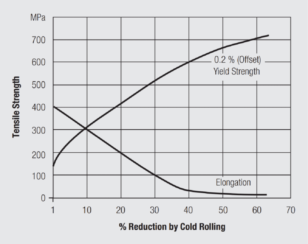
The cold rolling process takes the strip down from the hot rolling thickness of ten millimeters (0.4inches) to the final specified strip thickness, say 0.4 millimeters (0.016 inches). During the cold rolling process the yield strength and elongation of the strip are also established. Recall that deformation of a metal, in this case reduction in thickness by rolling, work hardens the metal increasing its resistance to deformation or increasing its yield strength. Work hardening also decreases the ductility of the metal, the amount of deformation it can support without cracking. This means that only a limited amount of reduction in thickness can be realized in cold rolling without damage to the strip. In practice a specified reduction in thickness is taken and the strip is then annealed, held at an elevated temperature for a specified time, to return it to its soft condition when it can then be subjected to another reduction in thickness. This roll/anneal process is repeated as often as necessary to get to the thickness required for the final annealing and rolling process which is when the mechanical properties of the strip are established. The final anneal establishes the final grain size of the strip, and the final reduction in thickness establishes the yield strength/elongation. The relationship between reduction in thickness and mechanical properties, in particular yield strength and elongation, is known for each copper alloy. A generalized example is provided in Figure 1.30. For a given connector design, the design yield strength is determined by the contact normal force requirement, as will be discussed in Chapter II/2.2 Contact Springs. The elongation requirement depends on the forming necessary to realize the conformation of the contact spring. As an example, say a cantilever beam receptacle contact normal force requirement dictates a yield strength of 500 MPa (75 ksi) and an elongation of greater than 5 percent is necessary. For the material indicated in Figure 1.30, a 30 percent reduction in thickness on the final cold rolling pass will meet the yield strength requirement with an elongation of just under 10 percent, which also meets the elongation/ductility requirements.
This description of the hot and cold rolling processes taking a copper alloy from a cast slab to a specified strip thickness and mechanical condition is, in principle, very straightforward. But the process controls, both thermal and mechanical, are very demanding as is the surface condition of the rolls and the supporting structures of the rolling mills that are used. Tradeoffs among the various thermal and rolling process variables used by copper strip providers explains the variation in the comparative relationship between yield strength and formability among suppliers.
Connector Contact Stamping and Forming
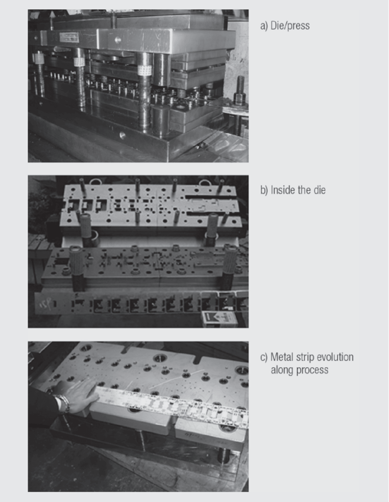
Stamping process is used to convert blank metal strip into contacts or shields by cutting and forming it. The press brings the pressure to the die which performs cutting and forming steps.
Figure 1.31a illustrates the die into the press, when figure b shows inside the die (in between the two parts). On the c figure we can see the metal strip evolution along the process (from a blank metal strip down to a typical RJ45 metallic shielding)
The vast majority of connector contacts are produced by stamping and forming processes using multi station dies that perform a variety of stamping operations including piercing, blanking, shearing and bending among others. The design of the dies and the sequence of the various stations depend on the complexity of the contact design with receptacle contacts being mostly more complex than those of plug contacts.
Copper Alloys
Copper alloys are commonly divided into several categories depending on the alloying element(s) and the amount of alloying. The dominant strengthening mechanism varies according to the same parameters as noted above.
Some general comments on the alloy families, based on categories used by the Copper Development Association, follow. The discussion is general due to the process dependence of mechanical properties. Alloy data should be obtained from the manufacturers.
Coppers: Coppers are a minimum of 99.3 percent copper. They are high conductivity alloys, greater than 80 percent IACS, with varying strength levels and stress relaxation resistance depending on the alloying elements. Principal alloying elements are phosphorus, magnesium and zirconium. DSP hardening is realized by copper-zirconium and magnesium-phosphorus particles.
High Coppers: High coppers are a minimum of 96 percent copper. Principal alloying elements include beryllium, chromium, cobalt, magnesium and iron. The beryllium alloys are PH strengthened. They have the highest strength, best stress relaxation resistance and lowest conductivities of the high coppers. The others are DSP strengthened by phosphide intermetallic compounds. They include a range of mechanical properties due to their different responses to second phase strengthening, moderate to good stress relaxation resistance and moderate conductivities.
Brasses: Brasses are copper/zinc alloys. Cartridge brass, 30 percent zinc, is the most highly alloyed connector material. Brass is unusual in that the addition of zinc to copper has a much lower effect on conductivity than any other alloying element, the conductivity of cartridge brass is 28 percent IACS. Brasses have moderate strength, stress relaxation resistance and conductivity.
There are two categories of modified brasses. Tin brasses use the alloy strengthening of tin to realize higher strength levels with lower work hardening which enhances the formability and stress relaxation resistance of the alloy.
The second category uses DSP hardening through additions of iron, cobalt, aluminum and silicon. Depending on the alloy, grain refinement, enhanced work hardening response, or combinations of both, provide additional strength for a given amount of cold working.
Bronzes: Classic bronzes are copper-tin alloys with the tin providing strong alloy hardening and enhanced cold working response. Tin additions dramatically reduce conductivity with the commonly used 5 and 8 percent tin alloys being less than 20 percent IACS. These alloys are commonly called phosphor bronzes because of the residual phosphorus from the deoxidizing process remaining in the alloy. Bronzes have high strength capability and good stress relaxation resistance. Modified bronzes using copper-aluminum and copper-silicon base alloys are also used.
Copper-nickel-silicon: Copper-nickel-silicon alloys having a combination of high strength, good stress relaxation resistance and moderate conductivity have been developed recently and are seeing increasing use in automotive applications.