Passive Components Blog
No Result
View All Result
  • Home
  • News
    • All
    • Aerospace & Defence
    • Antenna
    • Applications
    • Automotive
    • Capacitors
    • Circuit Protection Devices
    • electro-mechanical news
    • Filters
    • Fuses
    • Inductors
    • Industrial
    • Integrated Passives
    • inter-connect news
    • Market & Supply Chain
    • Market Insights
    • Medical
    • Modelling and Simulation
    • New Materials & Supply
    • New Technologies
    • Non-linear Passives
    • Optoelectronics and Isolation
    • Oscillators
    • Passive Sensors News
    • Resistors
    • RF & Microwave
    • Telecommunication
    • Weekly Digest
    Vishay Sfernice D2TO and DTO thick-film SMD power resistor sample kits with TO-263 D2PAK and TO-252 DPAK devices

    Vishay SMD Power Resistor Sample Kits for High-Power Design

    schurter-tcsv4-side-actuated-smt-tactile-switch

    SCHURTER Introduces Side-Actuated SMT Tactile Switch

    TLVR multiphase coupled inductors, auxiliary ballast inductor

    TLVR Coupled Inductors: Fast Load-Step Response and Current-Dependent Ballast-Inductor Optimisation

    Bourns CRH2512 2512 surface-mount metal-alloy current-sense resistor for high-current low-ohmic measurement

    Bourns CRH2512 5 W Current-Sense Resistors

    Littelfuse AK-FL FlatSuppressX axial-leaded bidirectional TVS diodes for high-voltage aviation DC power protection

    Littelfuse AK-FL TVS Diodes for Aviation DC Power Rails

    Rheinmetall Pierburg Pump Technology NanoLam DC-link capacitors for high-power electric vehicle traction inverter applications

    Rheinmetall Funds NanoLam Capacitor Production Scale-Up

    Bourns CSS4C-1216 four-terminal metal-strip current sense resistor for high-current Kelvin measurement

    Bourns Extends 1216 Kelvin Current Sense Resistors

    Modelithics COMPLETE+3D Library v26.3 for Ansys HFSS with RF passive component and 3D electromagnetic simulation models

    Modelithics COMPLETE+3D v26.3 Expands HFSS RF Models

    Samsung Electro-Mechanics low-profile and embedded MLCCs for compact PCB and power-delivery applications

    Samsung Low-Profile and Embedded MLCCs for Compact Devices

    Trending Tags

    • Ripple Current
    • RF
    • Leakage Current
    • Tantalum vs Ceramic
    • Snubber
    • Low ESR
    • Feedthrough
    • Derating
    • Dielectric Constant
    • New Products
    • Market Reports
  • Knowledge Blog
  • Dossiers
    • AI Hardware Dossier
    • Automotive Dossier
    • Industrial Robotics Dossier
    • Power Converter Dossier
    • Capacitor Dossier
    • Resistor Dossier
    • Inductor Dossier
    • Circuit Protection Dossier
  • Suppliers
    • Who is Who
  • PCNS
    • PCNS 2025
    • PCNS 2023
    • PCNS 2021
    • PCNS 2019
    • PCNS 2017
  • Events
  • Home
  • News
    • All
    • Aerospace & Defence
    • Antenna
    • Applications
    • Automotive
    • Capacitors
    • Circuit Protection Devices
    • electro-mechanical news
    • Filters
    • Fuses
    • Inductors
    • Industrial
    • Integrated Passives
    • inter-connect news
    • Market & Supply Chain
    • Market Insights
    • Medical
    • Modelling and Simulation
    • New Materials & Supply
    • New Technologies
    • Non-linear Passives
    • Optoelectronics and Isolation
    • Oscillators
    • Passive Sensors News
    • Resistors
    • RF & Microwave
    • Telecommunication
    • Weekly Digest
    Vishay Sfernice D2TO and DTO thick-film SMD power resistor sample kits with TO-263 D2PAK and TO-252 DPAK devices

    Vishay SMD Power Resistor Sample Kits for High-Power Design

    schurter-tcsv4-side-actuated-smt-tactile-switch

    SCHURTER Introduces Side-Actuated SMT Tactile Switch

    TLVR multiphase coupled inductors, auxiliary ballast inductor

    TLVR Coupled Inductors: Fast Load-Step Response and Current-Dependent Ballast-Inductor Optimisation

    Bourns CRH2512 2512 surface-mount metal-alloy current-sense resistor for high-current low-ohmic measurement

    Bourns CRH2512 5 W Current-Sense Resistors

    Littelfuse AK-FL FlatSuppressX axial-leaded bidirectional TVS diodes for high-voltage aviation DC power protection

    Littelfuse AK-FL TVS Diodes for Aviation DC Power Rails

    Rheinmetall Pierburg Pump Technology NanoLam DC-link capacitors for high-power electric vehicle traction inverter applications

    Rheinmetall Funds NanoLam Capacitor Production Scale-Up

    Bourns CSS4C-1216 four-terminal metal-strip current sense resistor for high-current Kelvin measurement

    Bourns Extends 1216 Kelvin Current Sense Resistors

    Modelithics COMPLETE+3D Library v26.3 for Ansys HFSS with RF passive component and 3D electromagnetic simulation models

    Modelithics COMPLETE+3D v26.3 Expands HFSS RF Models

    Samsung Electro-Mechanics low-profile and embedded MLCCs for compact PCB and power-delivery applications

    Samsung Low-Profile and Embedded MLCCs for Compact Devices

    Trending Tags

    • Ripple Current
    • RF
    • Leakage Current
    • Tantalum vs Ceramic
    • Snubber
    • Low ESR
    • Feedthrough
    • Derating
    • Dielectric Constant
    • New Products
    • Market Reports
  • Knowledge Blog
  • Dossiers
    • AI Hardware Dossier
    • Automotive Dossier
    • Industrial Robotics Dossier
    • Power Converter Dossier
    • Capacitor Dossier
    • Resistor Dossier
    • Inductor Dossier
    • Circuit Protection Dossier
  • Suppliers
    • Who is Who
  • PCNS
    • PCNS 2025
    • PCNS 2023
    • PCNS 2021
    • PCNS 2019
    • PCNS 2017
  • Events
No Result
View All Result
Passive Components Blog
No Result
View All Result

Design for Reliability: How Stress Simulations Can Help

27.11.2019
Reading Time: 5 mins read
A A

Source: EE Times article

By Balaji Siva Prasad Emandi. A method for simulating stress and faults early in the design phase to aid in the “Design for Reliability” of a product. Reliability of a product is the probability for it to perform the intended functions without failure under stated conditions for a stated period of time. This number plays a pivotal role in the success of the product apart from other factors, such as efficiency, ease of use, etc. A product with poor reliability not only degrades the customer’s experience but also deteriorates the company’s reputation in addition to increased service and warranty costs.

RelatedPosts

AVX Releases High-Temperature 150°C Glass-Encapsulated Multilayer Varistors

Most Reliable, Most Efficient and Price Effective Solid Tantalum Capacitors

COTS procurement for space missions

Stress on a component is a key parameter affecting the time for which it can function well. For example, if the datasheet specification of absolute maximum gate to source voltage rating of a power MOSFET is 20V, it is driven at voltages less than 15V. This is done to make sure that the voltage stress on the silicon dioxide layer between the gate and source is minimized while ensuring that the device turn-on occurs at the right instants.

This way, the ratings of the components in a design are selected to have sufficient margins. If the devices are selected with higher rating margins, the product becomes bulky and costly. Alternatively, if devices are selected with lesser or insufficient rating margins, they are over stressed, which could lead to early failures. Performing stress analysis and fault analysis for various fault conditions and operating conditions help to analyze the stress on the components and to assess the reliability.

This blog introduces a method of simulating stress and faults early in the design phase to aid in the “Design for Reliability” of a product. This can be achieved by using an industry-proven multi-domain system design simulation software.

Reliability and the bathtub curve

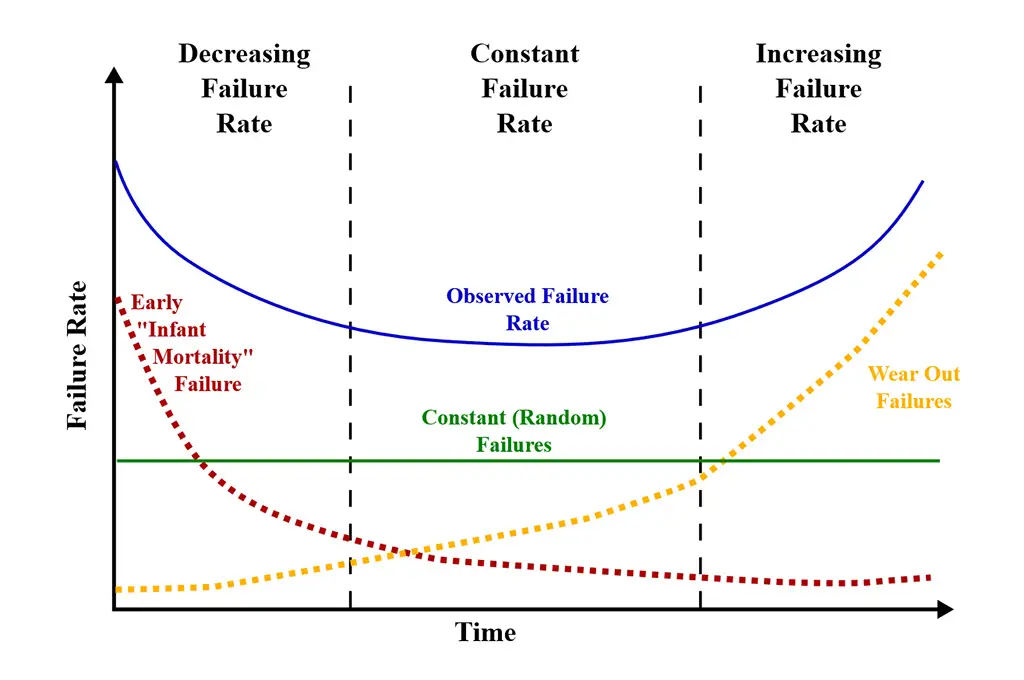
Let us take a peek at the reliability curve that designates the failure rate of a product over its lifecycle.

See featured image: Bathtub curve of Failure Rate; image source: Wikipedia

 The failure rate curve is comprised of three parts:

1.     Decreasing failure rate early in the life – Primary causes of these failures are improper design, bad manufacturing practices, etc. The failure rate is high initially but rapidly decreases as defective products are identified and discarded, and early sources of potential failures are surmounted. These failures can be avoided or minimized before production by performing various nominal analysis and stress analysis in design phase using a simulation tool.

2.     Constant failure rate during mid-life – During this phase in the lifetime, the failure rate is low and constant. These failures occur randomly, and the reasons are multifold (e.g. bad weather conditions, insulation failures, operational misuse, etc.). Performing Monte Carlo simulation, worst case, and automatic fault analysis for various scenarios using a simulation tool helps to avoid or minimize these failures.

3.     Increasing failure rate at the end of life – Late in the life of the product, the failure rate increases as age and wear take their toll. Performing parametric sweeps and stress analysis with de-rated parameters can help account for such factors in the design phase itself and extend the product life.

All these failures that occur at various stages in the lifecycle of a product end up costing the manufacturer in terms of service and warranty costs. A simulation tool can help to avoid or reduce these failures and decrease the cost significantly.

Design for reliability calculates the reliability of a design, the selection of margins on component ratings, the duration of burn-in tests, and so on. The inputs to such an analysis are the operating stress of the components, the ratings of the components selected, the likelihood of failure under different conditions, the availability of redundancy, etc. Common practice is to estimate the operating conditions from existing designs and arrive at an approximate reliability. With the availability of advanced simulation tools, it is easy to predict the behavior of a design under different conditions, such as conditions that are likely to occur in field and provide accurate inputs to reliability calculations. This helps to optimize the design for higher reliability during design phase on simulation platforms even before a hardware prototype is built.

Stress analysis

Stress on a component is a measure of the ratio of the actual quantity (voltage/current/power/temperature) applied on it when it is placed in an electrical circuit to its maximum rating. For instance, if the power rating of a resistor is 0.25 watt and the actual power dissipation in it when connected in an electrical circuit is 0.20 watt, the stress on the resistor is 80%. This value is normally estimated based on the experience of the electric circuit and calculations, if available. It becomes more difficult and inaccurate when the number of components in the design increases with each component having several rating parameters such as voltage, current, average power, peak power, etc. Measuring the operating stress on all the components through hardware measurements is nearly impossible due to the requirement of advanced measuring equipment, rework on the hardware to make the measurements, experimental setup to test various operating scenarios, and the potential safety risk to the test engineers.

In addition, it is standard practice to use a derating factor to account for wear and tear, and to design the system with sufficient margins. This is also called Factor of Safety (FoS). Accounting for derating factors and calculating the stress ratios manually for reliability analysis is very cumbersome.

When a simulation tool is used, the reliability analysis can be easily done. Derating factors can be applied to the parameters in stress analysis simulations and the ratio of the operating condition to the de-rated rating value is calculated as the stress ratio. So, in the simulation environment, the designer will be able to predict the stress on each component accurately and thereby size the components adequately. Without such analysis, the ratings selected might have huge margins resulting in increased cost and bulky components, which are contrary to the common industry requirements such as “reduced costs” and “smallest possible footprint.”

The main requirements for stress analysis are the availability of accurate simulation models and the ability to include the ratings that the datasheets of the components provide. In addition to this, the simulation tool should be able to predict the circuit behavior precisely and accommodate all the operating conditions to perform a comprehensive analysis. When the operating conditions are known, the tool should compare the simulated results with the ratings of the components and provide a user-friendly report that displays the stress ratios.

Using simulation early in the design phase helps to analyze the performance of the design well in advance, even before going to a hardware prototype. Performing advanced analysis, such as stress analysis, will result in optimal designs that need a lesser number of hardware iterations. The natural outcome is that the designs can be more robust with a shortened development cycle time and reduced cost.

SaberRD is a simulation platform capable of performing advanced system level simulation using accurate component models.
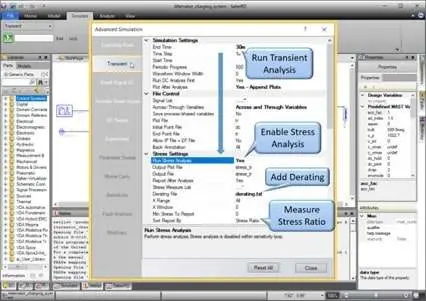
Transient Analysis with Stress Simulation as run in SaberRD
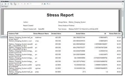
Stress Analysis Report as run in SaberRD

When a Stress Analysis is performed along with Fault Analysis, the results are more interesting. The designer can predict the components that might eventually fail when a fault occurs by looking at the stress report and the simulation results for all fault scenarios.

This method of virtual verification of stress on different components helps to optimize the reliability of the design with accurate measurements instead of subjective estimations and experience. The stress on the components is calculated using the analytical method and the ratings are selected appropriately. This helps to minimize design failures and lengthens the flat portion of the bathtub curve reducing the service and warranty costs for the manufacturer.

Simulation also offers a great reduction in design expenditure along with shortened development cycle time.


Balaji Siva Prasad Emandi
Balaji Siva Prasad Emandi is a Corporate Application Engineer for Saber in the Verification Group at Synopsys. Balaji enthusiastically supports pre- and post-sales customers in the domain of simulation and development of Power Electronic subsystems.


Related

Recent Posts

Vishay Sfernice D2TO and DTO thick-film SMD power resistor sample kits with TO-263 D2PAK and TO-252 DPAK devices

Vishay SMD Power Resistor Sample Kits for High-Power Design

25.9.2026
1
TLVR multiphase coupled inductors, auxiliary ballast inductor

TLVR Coupled Inductors: Fast Load-Step Response and Current-Dependent Ballast-Inductor Optimisation

24.9.2026
12
Bourns CRH2512 2512 surface-mount metal-alloy current-sense resistor for high-current low-ohmic measurement

Bourns CRH2512 5 W Current-Sense Resistors

24.9.2026
2
Littelfuse AK-FL FlatSuppressX axial-leaded bidirectional TVS diodes for high-voltage aviation DC power protection

Littelfuse AK-FL TVS Diodes for Aviation DC Power Rails

24.9.2026
11
Rheinmetall Pierburg Pump Technology NanoLam DC-link capacitors for high-power electric vehicle traction inverter applications

Rheinmetall Funds NanoLam Capacitor Production Scale-Up

22.9.2026
41
Bourns CSS4C-1216 four-terminal metal-strip current sense resistor for high-current Kelvin measurement

Bourns Extends 1216 Kelvin Current Sense Resistors

22.9.2026
17
Samsung Electro-Mechanics low-profile and embedded MLCCs for compact PCB and power-delivery applications

Samsung Low-Profile and Embedded MLCCs for Compact Devices

21.9.2026
22

Bourns Adds ACXX57SQ Air Coil Inductors for RF Design

18.9.2026
15
Samsung Electro-Mechanics MLCC capacitor solutions for high-voltage converter snubbing and GPU power delivery

Samsung MLCC Options for 1 MW AI Rack Power

18.9.2026
30

Upcoming Events

Sep 29
16:00 - 17:00 CEST

Cybersecurity 2026

Sep 30
15:00 - 16:00 CEST

Positronic Space and Military Connectors

Oct 14
17:00 - 18:00 CEST

Live Demo! Discover KYOCERA AVX Antenna Integrator Studio (AIS)

View Calendar

Popular Posts

  • Buck Converter Design and Calculation

    0 shares
    Share 0 Tweet 0
  • LLC Resonant Converter Design and Calculation

    0 shares
    Share 0 Tweet 0
  • Boost Converter Design and Calculation

    0 shares
    Share 0 Tweet 0
  • Flyback Converter Design and Calculation

    0 shares
    Share 0 Tweet 0
  • Capacitor Charging and Discharging

    0 shares
    Share 0 Tweet 0
  • Resistor Symbols

    0 shares
    Share 0 Tweet 0
  • Thermistors Basics, NTC and PTC Thermistors

    0 shares
    Share 0 Tweet 0
  • Audio Capacitors: Choosing Capacitors for Crossover Circuits

    0 shares
    Share 0 Tweet 0
  • MLCC and Ceramic Capacitors

    0 shares
    Share 0 Tweet 0
  • Capacitor Symbols

    0 shares
    Share 0 Tweet 0

Newsletter Subscription


Passive Components Blog

© 2015–2026
All rights reserved

  • Home
  • Privacy Policy
  • EPCI Membership & Advertisement
  • About

No Result
View All Result
  • Home
  • Knowledge Blog
  • Dossiers
  • PCNS

© 2015–2026
All rights reserved