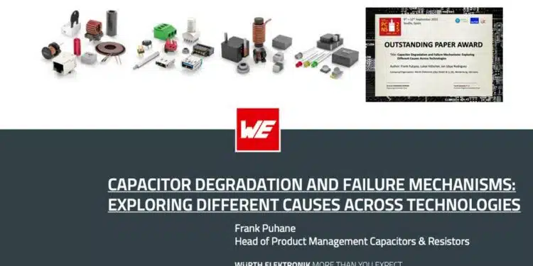
The paper “Capacitor Degradation and Failure Mechanisms: Exploring Different Causes Across Technologies” was presented by Frank Puhane, Würth Elektronik eiSos GmbH & Co.KG, Waldenburg, Germany at the 5th PCNS Passive Components Networking Symposium 9-12th September 2025, Seville, Spain as paper No. 2.7.
This paper was selected and awarded by TPC Technical Program Committee as the:
OUTSTANDING PAPER AWARD
Introduction
This article presents a comprehensive study of how various capacitor types age, degrade, and eventually fail. Capacitors are a crucial yet failure-prone component in power supply and electronic systems. The paper clearly distinguishes between capacitor degradation (wear-out) and total failure, and it explores how environmental, electrical, and material factors influence both phenomena across technologies such as aluminum electrolytic capacitors, aluminum polymer, hybrid polymer, metallized film capacitors, multilayer ceramic capacitors (MLCCs), and supercapacitors (EDLCs).
Key Takeaways
- The paper highlights the distinction between capacitor degradation (wear-out) and total failure, emphasizing technology-specific mechanisms for various capacitors.
- Environmental factors like temperature and humidity significantly impact capacitor aging, affecting reliability and performance across different types.
- Case studies demonstrate measurable degradation outcomes influenced by stress factors, including weight loss in electrolytic capacitors and capacitance drift in MLCCs.
- Accurate capacitor lifetime predictions require tailored models that consider specific degradation mechanisms and operational stress rather than relying on traditional FIT and MTBF metrics.
Extended Summary
The article begins by clarifying the difference between capacitor degradation—a progressive reduction in performance—and total failure. While FIT and MTBF provide statistical reliability measures, they often overestimate practical lifetime because they do not predict when a capacitor can no longer fulfill its functional role in a circuit.
The paper thoroughly examines various capacitor technologies. Metallized film capacitors are sensitive to temperature, humidity, and AC voltage, with electrochemical corrosion being the critical failure mechanism under harsh conditions. Lifetime modeling often uses Arrhenius or Eyring laws, but parameters vary significantly among manufacturers. Aluminum electrolytic capacitors primarily degrade through electrolyte evaporation accelerated by high temperatures. Their lifetime is commonly modeled with Arrhenius-based formulas incorporating temperature, voltage, and ripple current effects. Aluminum polymer and hybrid polymer capacitors avoid electrolyte dry-out but are sensitive to humidity, which increases ESR over time, while capacitance remains stable.
Multilayer ceramic capacitors (MLCCs) have undergone major changes with the adoption of base-metal electrodes and miniaturization. BME MLCCs are prone to insulation resistance degradation due to oxygen vacancy electromigration and are very sensitive to mechanical stress. High CV density and thin dielectrics make them more vulnerable to cracking, which may lead to long-term reliability issues. Supercapacitors (EDLCs) show degradation under prolonged voltage stress due to slow faradaic reactions and electrolyte aging. Long-term endurance tests demonstrate that ESR and capacitance loss occur in two phases, with the initial period showing the fastest changes.
The article also includes case studies that quantify how environmental and operational conditions affect performance over time. For electrolytic capacitors, weight loss correlates with capacitance reduction under high-temperature endurance tests. Polymer and hybrid capacitors show ESR increases under 85°C/85% RH stress without significant capacitance loss. Metallized film capacitors exposed to 85°C/85% RH with AC voltage reveal rapid early capacitance drop, while THB-rated variants fare better. MLCCs demonstrate long-term voltage-dependent capacitance drift, and supercapacitors exhibit extended lifetimes under room-temperature, rated-voltage conditions with gradual performance decay.
Finally, the authors emphasize that lifetime estimation should be tailored to each capacitor type and application. FIT/MTBF provides statistical reliability for large populations but does not define practical end-of-life. Predictive methods incorporating environmental and operational factors—potentially enhanced with physics-based machine learning—are increasingly valuable for real-world reliability assurance.
Chapter 1: Degradation vs. Failure
Degradation is characterized by progressive changes in capacitance and equivalent series resistance (ESR), while failure is defined as the inability of the capacitor to meet its functional role. Traditional reliability metrics such as FIT (Failures in Time) and MTBF (Mean Time Between Failures) provide statistical averages but often fail to capture the practical end-of-life behavior of individual components.
| Aspect | Degradation | Failure |
|---|---|---|
| Definition | Gradual performance loss | Complete functional breakdown |
| Metrics | Capacitance drift, ESR increase | FIT, MTBF |
| Predictability | Progressive, measurable | Often sudden |
| Impact | Reduced efficiency | System malfunction |
Chapter 2: Technology-Specific Mechanisms
2.1 Aluminum Electrolytic Capacitors
Aluminum electrolytic capacitors (AECs) rely on a liquid electrolyte to maintain conductivity between the etched aluminum anode foil and the cathode. The dielectric is a thin anodized Al2O3 layer. Over time, electrolyte evaporation becomes the dominant degradation mechanism, especially at elevated temperatures. This evaporation reduces ionic conductivity, leading to increased ESR and reduced capacitance. Ripple current accelerates internal heating, further driving electrolyte loss. Failure typically manifests as open-circuit behavior, though in rare cases dielectric breakdown can cause short circuits.
Key degradation accelerators include:
- Temperature: Every 10°C rise approximately halves the expected lifetime (Arrhenius rule).
- Ripple current: Generates localized heating, compounding evaporation.
- Voltage stress: Excessive applied voltage accelerates dielectric thinning and leakage current growth.
2.2 Aluminum Polymer and Hybrid Capacitors
Polymer capacitors replace the liquid electrolyte with a conductive polymer, eliminating evaporation issues. Hybrids combine polymer with a small amount of liquid electrolyte, balancing ESR performance with improved voltage endurance. The primary degradation factor is humidity ingress, which increases ESR without significantly affecting capacitance. Polymer capacitors typically fail in an open mode, while hybrids may also exhibit leakage current growth under extreme stress.
Distinctive features:
- Stable capacitance: Even under stress, capacitance remains nearly constant.
- ESR sensitivity: ESR rises under 85°C/85% RH conditions, limiting high-humidity applications.
- Failure modes: Open-circuit (dominant), occasional short-circuit under overload.
2.3 Metallized Film Capacitors
Film capacitors use thin polymer films (e.g., polypropylene) with vacuum-deposited metallization. They exhibit excellent self-healing properties: localized dielectric breakdown vaporizes the metallization around the defect, isolating the fault. However, under high humidity and AC stress, electrochemical corrosion of the metallization occurs, leading to capacitance loss. This is particularly critical in non-hermetic packages where moisture ingress is unavoidable.
Key points:
- Self-healing: Extends functional life but cumulative events reduce capacitance.
- Humidity + AC voltage: Accelerates corrosion, especially in polypropylene films.
- THB-rated variants: Designed for 85°C/85% RH endurance, showing slower degradation.
2.4 Multilayer Ceramic Capacitors (MLCCs)
MLCCs with base-metal electrodes (BME) are highly miniaturized, enabling high CV density. Their main vulnerabilities are:
- Mechanical stress: Board flexing, thermal cycling, or improper soldering can induce cracks in the brittle ceramic body.
- Insulation resistance degradation: Oxygen vacancy migration within BaTiO3 dielectric reduces IR over time, especially under DC bias.
- Voltage-dependent capacitance drift: Thin dielectrics and high fields accelerate long-term drift.
Cracks may not cause immediate failure but facilitate moisture ingress, leading to time-dependent dielectric breakdown.
2.5 Supercapacitors (EDLCs)
Supercapacitors store energy via electric double-layer capacitance and pseudocapacitive faradaic reactions. Their degradation is driven by:
- Electrolyte aging: Solvent decomposition and ion depletion reduce conductivity.
- Faradaic side reactions: Slow, irreversible reactions at the electrode/electrolyte interface increase ESR.
- Voltage stress: Prolonged operation at rated voltage accelerates both ESR rise and capacitance fade.
Degradation typically follows a two-phase curve: rapid ESR increase in the early phase, followed by gradual capacitance decay.
Chapter 3: Environmental and Operational Stress Factors
Capacitor reliability is strongly influenced by external stresses. Temperature, humidity, voltage, and mechanical forces act synergistically, often accelerating degradation beyond simple additive effects.
| Stress Factor | Impact on Electrolytic | Impact on Polymer/Hybrid | Impact on Film | Impact on MLCC | Impact on Supercapacitor |
|---|---|---|---|---|---|
| Temperature | Electrolyte evaporation | Accelerates ESR rise | Polymer shrinkage | Thermal mismatch cracking | Electrolyte decomposition |
| Humidity | Leakage increase | ESR increase | Corrosion of metallization | Moisture-assisted breakdown | Electrolyte contamination |
| Voltage | Dielectric thinning | Leakage growth | Accelerated corrosion | IR degradation | Faradaic side reactions |
| Mechanical Stress | Seal cracking | Terminal fatigue | Film delamination | Body cracking | Collector corrosion |
Chapter 4: Reliability Modeling
Reliability prediction requires models that capture the physics of degradation. Traditional FIT/MTBF values are insufficient for design-level assurance. Instead, engineers employ:
- Arrhenius models: Capture temperature acceleration of failure rates.
- Eyring models: Extend Arrhenius by including voltage, humidity, and mechanical stress terms.
- Physics-of-failure models: Directly simulate mechanisms such as electrolyte diffusion, corrosion kinetics, or vacancy migration.
- Machine learning approaches: Emerging methods that combine accelerated test data with field performance to predict lifetime more accurately.
Arrhenius Lifetime Model:
Eyring Model:
Chapter 5: Case Studies
Practical experiments illustrate how stress factors translate into measurable degradation:
- Electrolytic capacitors: High-temperature endurance tests show weight loss correlating with capacitance reduction. A 20% mass loss typically corresponds to a 30–40% capacitance drop.
- Polymer/Hybrid capacitors: Under 85°C/85% RH, ESR doubles within 1000 hours, while capacitance remains within ±5% of initial value.
- Film capacitors: Exposed to 85°C/85% RH with AC bias, capacitance drops by 10% within 500 hours. THB-rated variants show only 2–3% loss under identical conditions.
- MLCCs: Long-term DC bias tests reveal a logarithmic capacitance drift of up to 15% over 10,000 hours. Mechanical bending tests confirm crack initiation at board deflections as low as 2 mm.
- Supercapacitors: Endurance at rated voltage shows ESR doubling within the first 500 hours, followed by gradual capacitance fade of 20% over 2000 hours. At reduced voltage (70% of rated), lifetime extends by a factor of 3–4.
Conclusion
Capacitor degradation and failure mechanisms are highly technology-dependent, influenced by environmental and operational stress factors. Statistical reliability metrics such as FIT and MTBF provide population-level insights but fail to capture practical end-of-life behavior. Engineers must adopt tailored lifetime models, accelerated testing, and predictive analytics to ensure system reliability. By integrating advanced modeling approaches, including physics-based and machine learning methods, the industry can extend capacitor lifetimes and enhance the robustness of electronic systems.
The study highlights that capacitor lifetime and failure depend heavily on technology, environmental stress, and operating conditions. Accurate lifetime prediction requires distinguishing between statistical failure rates and practical end-of-life behavior. By analyzing degradation mechanisms, accelerated tests, and long-term studies across different capacitor technologies, the paper provides clear guidance for engineers designing high-reliability systems. Incorporating advanced modeling and predictive approaches can help in mitigating failures, extending service life, and improving the reliability of electronic systems where capacitors remain critical components.
Capacitor Degradation and Failure Mechanisms – FAQ
Degradation is a gradual loss of performance, such as reduced capacitance or increased ESR, while failure is a sudden event where the capacitor no longer functions. FIT and MTBF measure statistical reliability but do not define practical end-of-life.
High temperature, applied voltage, humidity, and mechanical stress are the main drivers of capacitor degradation. MLCCs are especially vulnerable to cracking from mechanical stress.
Electrolytic capacitors degrade through electrolyte evaporation, polymers through humidity-driven ESR increase, film capacitors through electrochemical corrosion, MLCCs through cracking and insulation resistance loss, and supercapacitors through electrolyte aging and faradaic reactions.
FIT and MTBF provide statistical averages but do not predict individual component lifetimes. Physics-based models and machine learning approaches offer more accurate lifetime predictions.
How to Improve Capacitor Reliability in Electronic Systems
- Select the right capacitor technology
Choose electrolytic, polymer, film, MLCC, or supercapacitors based on application needs, considering voltage, temperature, and mechanical stress factors.
- Control environmental conditions
Minimize exposure to high temperature, humidity, and vibration. Use protective coatings or enclosures where necessary.
- Apply derating strategies
Operate capacitors below their maximum rated voltage and temperature to extend service life and reduce stress-related failures.
- Use advanced lifetime prediction models
Incorporate Arrhenius/Eyring models or physics-based machine learning approaches to estimate realistic end-of-life behavior.
- Validate with accelerated testing
Perform endurance and stress tests (e.g., 85°C/85% RH) to confirm reliability under worst-case conditions before deployment.


