


Capacitors are foundational elements in electronics, yet their real-world behavior includes several parasitic elements.
Among these, the Equivalent Series Inductance (ESL) plays a critical role in high-speed digital and RF applications. This white paper aims to provide engineers with clear insights into ESL, its origin, analytical models, effects on circuit performance, and methods for reduction.
Key Takeaways
- Capacitor ESL refers to Equivalent Series Inductance, impacting performance in high-speed and RF applications.
- ESL arises from factors like electrode structure, lead/termination inductance, and PCB layout.
- To minimize ESL, use low-inductance capacitor types, optimize layouts, and measure or simulate during design.
- High-performance capacitors with low ESL are essential for efficient signal integrity and power stability.
- Industry trends focus on developing technologies that achieve ultra-low ESL for modern electronic circuits.
What is ESL?
Equivalent Series Inductance (ESL) is the inherent self-inductance present within a capacitor due to its physical structure, including internal electrodes, terminations, leads, and PCB mounting. While an ideal capacitor stores electrical energy purely in its electric field, all real capacitors have a tiny inbuilt inductor in series — this is their ESL. In effect, each capacitor becomes an RLC (Resistor-Inductor-Capacitor) network at operating frequencies above a few kilohertz.
Physical Origins of ESL
- Electrode Structure: The geometry, overlap, and arrangement of internal electrodes contribute to current paths that generate magnetic fields, leading to inductance.
- Lead/Termination Inductance: Wires, leads, PCB traces, and surface-mount terminations form loops through which current flows, adding to total inductance.
- Mounting and Layout: On PCBs, the separation of vias and the power/ground plane geometry can further increase the effective inductance.
Equivalent Circuit and Resonance
A practical capacitor’s equivalent circuit is composed of its ideal capacitance (C), Equivalent Series Resistance (ESR), and ESL. Insulation resistance in parallel to the ideal capacitor is add to reflect dielectric leakage current as shown in figure 1. below.
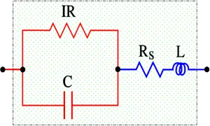
- C = Capacitance
- IR = Insulation Resistance (IR>>Rs)
- Rs = Series losses
- L = Inductance in lead-in wires (ESL)
At low frequencies, the capacitor acts ideally. However, as frequency increases, ESL starts to dominate, causing the capacitor’s impedance to stop decreasing and eventually rise. The frequency at which the capacitive and inductive reactances are equal is the self-resonant frequency (SRF):
Above the SRF, a capacitor acts more like an inductor than a capacitor.
Impact of ESL in Applications
- High-Speed Digital Circuits: Increased ESL leads to insufficient decoupling and voltage drops (ground/power bounce) during fast switching.
- RF and High-Frequency Circuits: Parasitic inductance results in unwanted resonance and signal integrity issues.
- Power Distribution Networks (PDN): High ESL reduces effectiveness in supplying transient load currents, especially for CPUs and FPGAs.
Factors Influencing ESL
- Package Type: SMD capacitors (especially reverse geometry and face-down terminations) generally exhibit much lower ESL than leaded types.
- Capacitor Size and Geometry: Smaller packages, more parallel terminations, and stacked constructions help minimize current loop area and, thus, ESL.
- PCB Layout: Minimizing the path between power/ground planes and using multiple vias reduces loop inductance.
Methods to Minimize ESL
- Use low-inductance capacitor constructions (LICC, reverse geometry MLCCs, polymer types).
- Optimize PCB layout with short, wide tracks and closely spaced power/ground vias.
- Place decoupling capacitors as close as possible to the power pins of ICs.
- Parallel several smaller MLCCs to reduce effective ESL through mutual cancellation effects.
Measurement and Simulation of ESL
- ESL can be measured using impedance analyzers or a network analyzer by locating the SRF and fitting the equivalent RLC circuit model.
- Software tools (e.g., SPICE, electromagnetic field solvers) can predict the impact of mounting and PCB layout on effective ESL.
Industry Trends
- Development of ultra-low inductance capacitor technologies for GHz-range applications.
- Integration of decoupling capacitance directly into IC packages and substrates.
The need to maintain high performance, miniaturise circuit, and control cost is the main driver towards new types of capacitors. Using advanced technologies, manufacturers are producing new types of capacitors to meet the performance requirements of today’s electronic circuits. High performance capacitors with very low ESLs are increasingly replacing conventional ceramic, tantalum, and aluminum capacitors. Tantalum polymer capacitors and aluminum polymer capacitors are some of the new solutions for decoupling applications in high performance circuits. These very low inductance capacitors occupy much less space and the cost of producing them is reasonable.
PARASITIC INDUCTANCE IN CERAMIC CAPACITORS
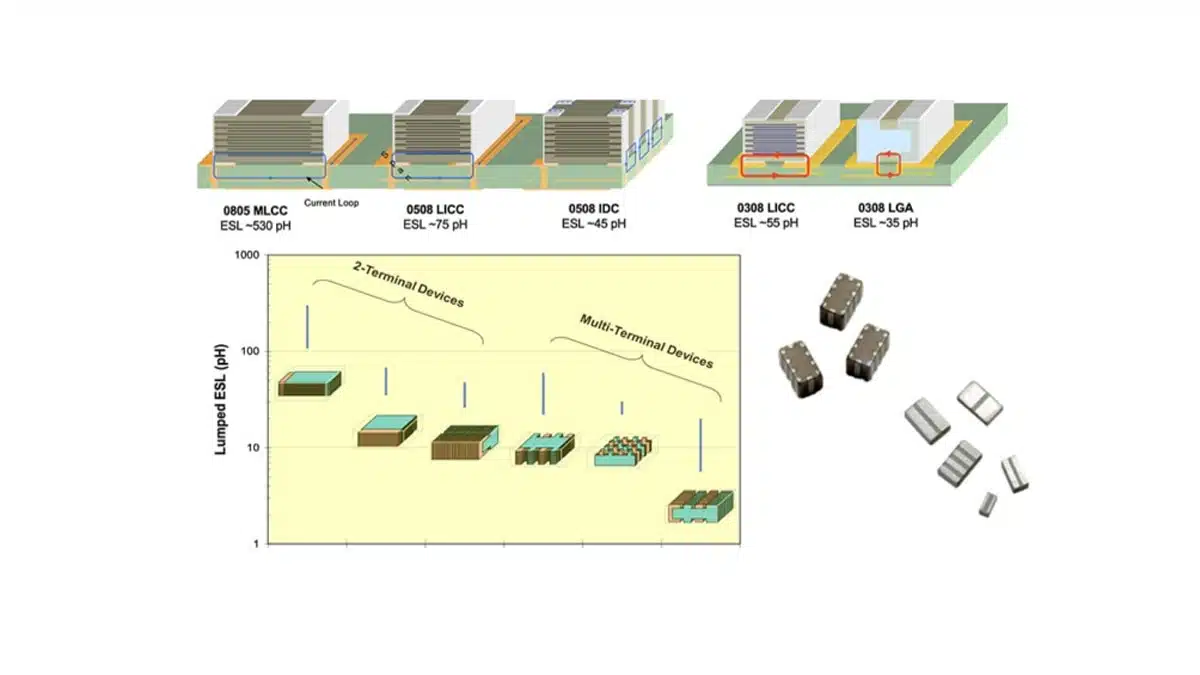
Ceramic capacitors are commonly used in electronic circuits for decoupling applications. The equivalent circuit model of a typical multilayer ceramic capacitor consists of three elements: the capacitor, series resistance, and parasitic inductance. For decoupling applications in high speed digital systems, the inductance of an MLCC is an important factor. This is because the ripple voltage is dependent on inductance. The current loop is the key physical characteristic that determines equivalent series inductance. ESL increases with an increase in the size of the current loop.
In chip capacitors, equivalent series inductance is greatly determined by the distance between terminations. Since capacitors with a smaller current loop have lower inductances, reducing the distance between terminations of a capacitor helps to reduce the size of the current loop. Using opposing current loops helps to further reduce equivalent series inductance in surface mount capacitors. Significant reduction in inductance can be achieved by optimizing the architecture of a surface mount capacitor.
In bypass capacitors, the resonant frequency is dependent on parasitic inductance. The effect of this parasitic component becomes more prevalent in high frequency applications. It is, therefore, critical for design engineers to measure the inductance of capacitors for high speed digital circuits.
In PCB mounted decoupling capacitors, inductance is mainly determined by the mounting pad structure. Current flows through the loop described by these three elements: capacitor height, power plane spreading, and pad layout. Since equivalent circuit inductance increases with an increase in the size of the current loop, it is minimized by ensuring that the power (Vdd) and ground (Gnd) vias are close to each other. Other ways of minimizing inductance include selecting a suitable pad layout design and using shorter vias.
High capacitance capacitors tend to have high ESLs, and vice versa. When designing digital circuits, engineers should consider both capacitance and equivalent series inductance. In high speed electronic circuits, low inductance multilayer ceramic capacitors are placed close to the load. As compared to conventional tantalum and aluminum capacitors, MLCCs have lower equivalent series inductance. If space is not an issue, MLCCs can be connected in parallel to provide very low equivalent series inductance.
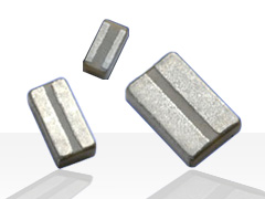
MLCC technologies are providing great level of design flexibility to suppress its self-inductance by various of design configurations and solutions. See example of right image: Low Inductance Ceramic Capacitors LICC.
PARASITIC INDUCTANCE IN TANTALUM CAPACITORS
Tantalum capacitors are commonly used in applications that demand high reliability and volumetric efficiency. Just like other types of capacitors, these capacitors have parasitic ESR and ESL. In tantalum capacitors, conduction currents flow through conductors of finite size. The parasitic inductance of tantalum capacitors is due to these conductors. The capacitance value of a tantalum capacitor has an almost negligible effect on the parasitic inductance. In addition, unlike ESR, the ESL of a tantalum capacitor remains fairly constant over a wide range of frequency. In tantalum capacitors, equivalent series inductance is minimized by using facedown terminations. Use of these terminations helps to reduce the loop area, thereby reducing parasitic inductance.
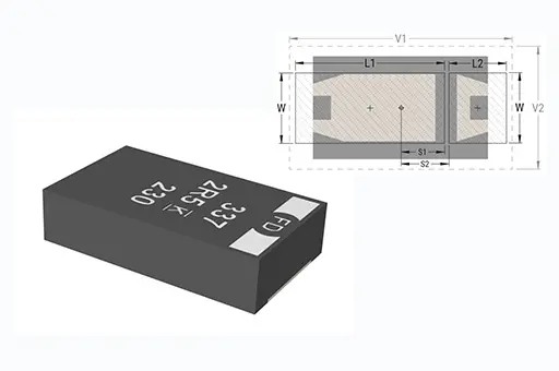
Traditionally, tantalum capacitors are limited to low frequency applications. The impressive performance of facedown (undertab) low inductance tantalum capacitors has created new applications for tantalum capacitors in power distribution networks (PDNs). For decoupling applications in high-performance digital circuits, low inductance tantalum polymer capacitors perform better than conventional ceramic and aluminum electrolytic capacitors. Other characteristics that make low inductance tantalum capacitors a suitable choice for high performance circuits include low ESR and moderately high capacitance.
PARASITIC INDUCTANCE IN ALUMINUM ELECTROLYTIC CAPACITORS
For a long time, electronic circuit designers have used wet aluminum electrolytic capacitors for bulk decoupling applications. However, the relatively high ESL and ESR of these capacitors slow their response and lower their performance. Aluminum polymer capacitors have better performance characteristics, and they are increasingly replacing wet aluminum capacitors in bulk decoupling applications. Unlike conventional aluminum capacitors, these newer capacitors use a conductive polymer as the electrolyte. In addition, the performance of valve-metal capacitors allows use of fewer components, thereby saving space and reducing cost.
In computers and other high performance digital circuits, aluminum polymer capacitors and tantalum polymer capacitors are used for bulk decoupling applications. In addition to very low ESL, these valve-metal capacitors have very low ESR, small footprint, high volumetric efficiency, and moderately high capacitance. However, as compared to conventional aluminum capacitors, valve-metal capacitors are more expensive to produce.
See also video: Axial Aluminum Electrolytic Capacitors’ ESL and its Measurement
CONCLUSION
ESL is a critical real-world property of capacitors that can significantly impact high-speed, high-performance electronics. Understanding and managing ESL enables engineers to ensure signal integrity, power stability, and efficient system operation. Careful selection of capacitor type, mounting strategy, and layout optimization are the keys to mitigating unwanted inductive effects in modern designs.
The speed at which energy is transferred to a load is greatly determined by the equivalent series inductance of a capacitor. This speed increases with a decrease in ESL. Today’s digital circuits have higher switching speeds and demand low inductance capacitors. The demand for capacitors with very low inductances continues to grow as the switching speeds increase.
Manufacturers are progressively advancing capacitor manufacturing technology to meet the performance demanded by today’s high speed digital circuits.
FAQ: ESL Capacitor Parasitic Inductance
ESL stands for Equivalent Series Inductance, which is the inherent inductance present within a capacitor due to its construction, including internal electrodes, leads, and PCB mounting. It causes a capacitor to behave not only as a capacitor but also as an inductor at higher frequencies.
SL affects a capacitor’s performance in high-speed digital and RF applications. High ESL can lead to resonance, signal integrity issues, and insufficient decoupling, impacting the stability of power and ground lines.
The SRF is the frequency where the capacitor’s capacitance and inductance reactances are equal and cancel. Above this frequency, the capacitor acts more like an inductor.
Key factors include package type (SMD vs. leaded), capacitor size, geometry, the arrangement of PCB traces, and mounting techniques. Smaller, low-inductance constructions and optimal PCB layouts reduce ESL.
Use low-inductance capacitor types, optimize PCB layouts with short, wide traces, place capacitors close to IC power pins, and parallel multiple MLCCs. Advanced designs like LICC and reverse geometry MLCCs further lower ESL.
ESL is measured using impedance or network analyzers by analyzing the SRF. Simulation software like SPICE can also predict ESL based on capacitor and PCB geometry.
Modern digital circuits have high switching speeds needing stable power and minimal noise. Proper ESL management ensures signal integrity, efficient decoupling, and reliable operation in high-speed electronic systems.
How To Minimize ESL in Capacitor Applications
- Select low-inductance capacitor types
Use reverse geometry MLCCs, LICC, or special capacitor designs for lower inherent inductance.
- Optimize PCB layout
Shorten and widen the traces, minimize the distance between power/ground vias, and ensure close placement of decoupling capacitors to IC pins.
- Parallel multiple capacitors
Connecting multiple small MLCCs in parallel reduces overall ESL due to mutual inductance cancellation. The exact reduction depends on the physical arrangement and mutual coupling between the capacitors. This effect allows for lower loop impedance at high frequencies, improving decoupling and power integrity in circuits
- Measure and simulate ESL during design
Use impedance or network analyzers to measure SRF and validate design with simulation tools like SPICE. Note to use the model of real capacitor not an ideal component.
- Choose advanced capacitor technologies for high-speed circuits
For GHz-range designs, consider ultra-low ESL technologies and integrated decoupling in IC packages.


