Passive Components Blog
No Result
View All Result
  • Home
  • NewsFilter
    • All
    • Aerospace & Defence
    • Antenna
    • Applications
    • Automotive
    • Capacitors
    • Circuit Protection Devices
    • electro-mechanical news
    • Filters
    • Fuses
    • Inductors
    • Industrial
    • Integrated Passives
    • inter-connect news
    • Market & Supply Chain
    • Market Insights
    • Medical
    • Modelling and Simulation
    • New Materials & Supply
    • New Technologies
    • Non-linear Passives
    • Oscillators
    • Passive Sensors News
    • Resistors
    • RF & Microwave
    • Telecommunication
    • Weekly Digest

    Choosing the Right Capacitor: The Importance of Accurate Measurements

    Littelfuse Releases TMR Switches with Ultra-Low Power Magnetic Sensing

    Skeleton Opens SuperBattery Factory in Finland 

    Kyocera Releases Ultra-Compact Low Voltage Clock Oscillators

    Murata Expands High Rel NTC Thermistors in Compact 0603M Size

    RF Inductors: Selection and Design Challenges for High-Frequency Circuits

    Wk 45 Electronics Supply Chain Digest

    Transformer Safety IEC 61558 Standard

    ESR of Capacitors, Measurements and Applications

    Trending Tags

    • Ripple Current
    • RF
    • Leakage Current
    • Tantalum vs Ceramic
    • Snubber
    • Low ESR
    • Feedthrough
    • Derating
    • Dielectric Constant
    • New Products
    • Market Reports
  • VideoFilter
    • All
    • Antenna videos
    • Capacitor videos
    • Circuit Protection Video
    • Filter videos
    • Fuse videos
    • Inductor videos
    • Inter-Connect Video
    • Non-linear passives videos
    • Oscillator videos
    • Passive sensors videos
    • Resistor videos

    Choosing the Right Capacitor: The Importance of Accurate Measurements

    RF Inductors: Selection and Design Challenges for High-Frequency Circuits

    Transformer Safety IEC 61558 Standard

    3-Phase EMI Filter Design, Simulation, Calculation and Test

    Transformer Design Optimization for Power Electronics Applications

    Common Mode Chokes Selection for RF Circuits in Next-Generation Communication Systems

    Capacitor Self-balancing in a Flying-Capacitor Buck Converter

    How to Select Ferrite Bead for Filtering in Buck Boost Converter

    Power Inductors Future: Minimal Losses and Compact Designs

    Trending Tags

    • Capacitors explained
    • Inductors explained
    • Resistors explained
    • Filters explained
    • Application Video Guidelines
    • EMC
    • New Products
    • Ripple Current
    • Simulation
    • Tantalum vs Ceramic
  • Knowledge Blog
  • Suppliers
    • Who is Who
  • PCNS
    • PCNS 2025
    • PCNS 2023
    • PCNS 2021
    • PCNS 2019
    • PCNS 2017
  • Events
No Result
View All Result
Passive Components Blog
No Result
View All Result

EMI Suppression in Spacecrafts

20.10.2021
Reading Time: 7 mins read
A A

NASA is ramping up efforts in space travel with the Mars Perseverance Rover, the Artemis program, and ultimately humans landing on Mars. This article by Steve Taranovich published by Electronic Design discuss a possible concern in space travel that’s not often mentioned: EMI in spacecraft.

Electromagnetic interference (EMI) can be a nuisance and even approach disastrous levels in outer space. NASA engineers take every precaution to verify any kind of flight hardware that goes into space.

RelatedPosts

Choosing the Right Capacitor: The Importance of Accurate Measurements

Littelfuse Releases TMR Switches with Ultra-Low Power Magnetic Sensing

Skeleton Opens SuperBattery Factory in Finland 

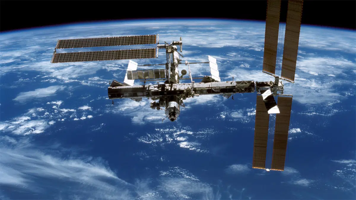
EMI on the International Space Station (ISS)

Back in the Space Shuttle program, the contact potential between the ISS and the Space Shuttle had been monitored on all docking missions. Langmuir probes, mounted on the ISS, had monitored contact potential between the ISS and any docking vehicle. No serious EMI effects were ever noted on any ISS or Space Shuttle equipment after docking.

NASA also published “Analysis of Radiated EMI from ESD events caused by Space Charging.” This effort used modeling to analyze conducted and radiated EMI caused by electrostatic-discharge (ESD) events in space. NASA engineers looked at surface charging, which could develop on the exterior of satellite surfaces, due to the interaction between those surfaces and the space plasma environment. NASA’s extensive research assessed charging mechanisms present when dielectric surfaces of any spacecraft become exposed to the space plasma environment, usually at geosynchronous Earth orbit (GEO) and POLAR orbits.

When ESD happens, stored charges are released. These create a discharge current that may generate conducted emissions, which happen when a replacement current originating as a charge is blown off a dielectric surface. This induces a replacement current flowing from a satellite or spacecraft structure.

Radiated emissions are generated by the ESD current pulse. When a rapid surface potential changes, the effect is noise induced in circuitry via capacitive coupling. Also, discharge currents can inductively induce a signal into a victim circuit. These inductive, capacitive, and field-to-circuit couplings are manifestations of transient radiated and conducted EMI.

ISS Power Filter Design for Conducted Emissions

Power-line conducted emissions also need to be controlled on the ISS to protect power quality, limit electric-field radiation, and control noise currents on vehicle structures. Because the ISS doesn’t use the radio-frequency (RF) spectrum below 100 MHz, there are no radiated emissions limits imposed on payloads below that frequency.

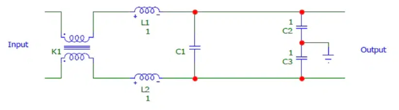
A manufacturer-designed filter Figure 1, prior to the publication of MIL-STD-461D, had a test source impedance using 10-mF feed-through capacitors. This filter is known as the 461B filter.

Figure1. The ISS 461B filter to suppress conducted emissions

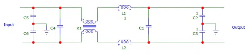
The filter design shown in Figure 2 came after the publication of MIL-STD-461D, where the source impedance had two 50-mH line impedance stabilization networks (LISNs). This filter is known as the 461D filter, which had both Y (line-to-ground) capacitors (C5 and C6) and an X (line-to-line) capacitor (C4) as its first elements, providing a mismatch with the high source impedance.

Figure 2. The 461D filter targeted to suppress conducted emissions

Mars Rover EMI

Power-conversion architectures on the Mars Rover include isolated dc-dc converters, point-of-load dc-dc converters, and EMI filters that power the camera system and processing on the Mars 2020 Rover.

Just about all of the data collected by NASA Mars Rovers returns to Earth through a relay link from the Mars surface to a Mars Reconnaissance Orbiter circling Mars. All of this science data comes from omnidirectional antennas for simplicity. However, this system is quite susceptible to RF interference coming from nearby science payloads and spacecraft subsystems, which downgrades link performance by a factor of 2+.

Most of the interference generates from Fourier overtones via switching power supplies, data lines, stepper motors, and clocks. This EMI on the spacecraft is pretty stable in frequency; however, the EMI tones’ complements will vary as the spacecraft operating mode changes.

An Adaptive EMI Mitigation study has developed computationally efficient algorithms that enable characterization and elimination of major tone interference. Such interference would degrade the data return performance from the Rover on the Mars surface to the relay orbiters overhead.

CubeSat Antenna EMI

Designing a monopole wire antenna is pretty simple for communication use on a CubeSat. A wire needs to be cut to a quarter-wavelength and a perpendicular half-wavelength ground plane must be created.

A 17.5-cm monopole is best for the CubeSat and will need a 35-cm ground plane formed by a parallel satellite surface. This ground plane would be too large for a CubeSat, so designers have to tune that wire antenna by cutting off small lengths until a desired return loss is achieved (monopole antennas can be very forgiving in reaching a desired return loss).

The perpendicular half-wavelength ground plane, which can be built using satellite external panels, needs to be constructed to provide electrical connectivity. Because RF current will flow through these panels, designers can expect a higher level of EMI influencing internal and external electronics for satellite operations. This influence will be most prevalent during transmission and will make sensor readings and bus voltages (especially I2C bus) unreliable. This may also affect transmitter electronics as well as microcontroller control of the transmitter. Installing proper electromagnetic shielding in place will help mitigate these effects.

Using a dipole antenna for the UHF band will provide overall better performance. However, the EMI problems will still exist if shielding isn’t properly applied.

CubeSats also may have an RF power supply to drive an electrothermal plasma micro-thruster. One example of such a power supply could be a 13.8-MHz, 14-V-input, 15-W design using air core inductors (Figure 3.).

Figure 3. Plasma inverter for a plasma load with a matching network

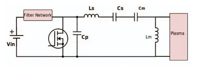
Air-core inductors are perfect for operation in a harsh environment because they don’t use magnetic cores, thus saving space. Faraday shielding is usually added to minimize radiated EMI. Conducted EMI may be minimized via a multi-resonant input filter using PCB inductors. Reference 5 goes into much greater detail for designers.

Summary

All of the vehicles that NASA sends into space must undergo extensive EMI testing. Many of the vehicles are huge while some are much smaller, but all of these electronic systems require testing in the environment in which they will operate—the cold vacuum void of outer space. NASA has constructed such test facilities to simulate this environment at their Glenn Research Center.

The space vehicles greatly vary in size from small satellites and CubeSats to vehicles such as the Mars Rover and other large launch vehicles. All of these spacecraft have electronic devices that need to operate properly in space with a very low failure rate.

Human life, of course, must be protected against any catastrophic failures that may be caused by EMI as the prime objective. The secondary objective is to protect the very expensive space vehicles against failures due to EMI radiation from electronics within these vehicles, as well as any possible EMI from spacecraft docking with other spacecraft. NASA has been very successful in these efforts.

References

1. Electromagnetic Interference Laboratory, Glenn Research Center, NASA

2. EMI from Spacecraft Docking Systems, NASA

3. Electromagnetic Compatibility Considerations for International Space Station Payload Developers, NASA Marshall Space Flight Center

4. Analysis of Radiated EMI from ESD events caused by Space Charging, NASA

5. A compact RF power inverter with reduced EMI for a CubeSat electrothermal micro-thruster, IEEE Xplore 2017

Related

Source: Electronic Design

Recent Posts

Choosing the Right Capacitor: The Importance of Accurate Measurements

12.11.2025
7

RF Inductors: Selection and Design Challenges for High-Frequency Circuits

10.11.2025
32

Transformer Safety IEC 61558 Standard

7.11.2025
15

ESR of Capacitors, Measurements and Applications

7.11.2025
60

3-Phase EMI Filter Design, Simulation, Calculation and Test

6.11.2025
60

YAGEO Unveils Compact 2.4 GHz SMD Antenna

6.11.2025
12

KYOCERA AVX Releases Antenna for Iridium Satellite IoT Applications

6.11.2025
14
Image credit: Samtec

How to Match the Right Connector with Protocol Requirements

6.11.2025
16

Transformer Design Optimization for Power Electronics Applications

4.11.2025
24

Upcoming Events

Nov 12
November 12 @ 12:00 - November 13 @ 14:15 EST

Microelectronic Packaging Failure Modes and Analysis

Nov 13
11:00 - 11:30 CET

DC/DC Converters in Automotive Applications

Nov 18
November 18 @ 12:00 - November 20 @ 14:15 EST

Design and Test of Non-Hermetic Microelectronics

View Calendar

Popular Posts

  • Buck Converter Design and Calculation

    0 shares
    Share 0 Tweet 0
  • Boost Converter Design and Calculation

    0 shares
    Share 0 Tweet 0
  • LLC Resonant Converter Design and Calculation

    0 shares
    Share 0 Tweet 0
  • Flyback Converter Design and Calculation

    0 shares
    Share 0 Tweet 0
  • Ripple Current and its Effects on the Performance of Capacitors

    3 shares
    Share 3 Tweet 0
  • Dual Active Bridge (DAB) Topology

    0 shares
    Share 0 Tweet 0
  • MLCC and Ceramic Capacitors

    0 shares
    Share 0 Tweet 0
  • What is a Dielectric Constant and DF of Plastic Materials?

    4 shares
    Share 4 Tweet 0
  • SEPIC Converter Design and Calculation

    0 shares
    Share 0 Tweet 0
  • What Electronics Engineer Needs to Know About Passive Low Pass Filters

    0 shares
    Share 0 Tweet 0

Newsletter Subscription


Passive Components Blog

© EPCI - Leading Passive Components Educational and Information Site

  • Home
  • Privacy Policy
  • EPCI Membership & Advertisement
  • About

No Result
View All Result
  • Home
  • Knowledge Blog
  • PCNS

© EPCI - Leading Passive Components Educational and Information Site

This website uses cookies. By continuing to use this website you are giving consent to cookies being used. Visit our Privacy and Cookie Policy.
Go to mobile version