




Passive Components Blog
No Result
View All Result
  • Home
  • News
    • All
    • Aerospace & Defence
    • Antenna
    • Applications
    • Automotive
    • Capacitors
    • Circuit Protection Devices
    • electro-mechanical news
    • Filters
    • Fuses
    • Inductors
    • Industrial
    • Integrated Passives
    • inter-connect news
    • Market & Supply Chain
    • Market Insights
    • Medical
    • Modelling and Simulation
    • New Materials & Supply
    • New Technologies
    • Non-linear Passives
    • Optoelectronics and Isolation
    • Oscillators
    • Passive Sensors News
    • Resistors
    • RF & Microwave
    • Telecommunication
    • Weekly Digest
    VACUUMSCHMELZE VACODUR Max cobalt-iron lamination material illustrated as thin metallic rotor and stator stacks.

    VACUUMSCHMELZE Introduced VACODUR Max Cobalt-Iron Alloy for Motor Laminations

    Stackpole RPCQ thick-film chip resistors in rectangular surface-mount packages with end terminations

    Stackpole Releases Pulse-Withstanding Chip Resistors up to 4 W

    Bourns CRT-G thin film chip resistor illustration with a rectangular body and metallic end terminations

    Bourns Introduces Precision Thin Film Resistors for Measurement

    Würth Elektronik ABC of Thermal Management textbook

    Würth Elektronik Launches ABC of Thermal Management Guide

    Schematic of six-arm nitrene crosslinker joining PEI polymer chains in a free-standing dielectric film.

    Crosslinked PEI Film Capacitor Dielectrics Reach 6 J/cm³ at 200°C

    Conceptual illustration of Peak Nano NanoPlex HDC capacitor dielectric film rolls beside a cast-film production line

    Peak Nano Scales NanoPlex HDC Capacitor Film Production 20-Fold

    Bourns Releases 450 V DC Bus TVS Diode

    YAGEO Nexensos M422 Pb-free platinum RTD graphic showing the operating temperature range, nominal resistance options and joining methods.

    YAGEO Introduces Pb-Free Platinum RTD Temperature Sensor

    Reference tantalum capacitor anode characterization, tantalum anode modeling, process selection and life-test verification.

    Tantalum Anode Design Combines Structural Benchmarks and Modeling

    Trending Tags

    • Ripple Current
    • RF
    • Leakage Current
    • Tantalum vs Ceramic
    • Snubber
    • Low ESR
    • Feedthrough
    • Derating
    • Dielectric Constant
    • New Products
    • Market Reports
  • Knowledge Blog
  • Dossiers
    • Aerospace and Defense Passive Components Dossier
    • AI Hardware Dossier
    • Automotive Dossier
    • Industrial Robotics Dossier
    • Power Converter Dossier
    • Capacitor Dossier
    • Circuit Protection Dossier
    • Inductor Dossier
    • Resistor Dossier
    • Silicon Capacitors and Integrated Passives Dossier
  • Suppliers
    • Who is Who
  • PCNS
    • PCNS 2025
    • PCNS 2023
    • PCNS 2021
    • PCNS 2019
    • PCNS 2017
  • Events
No Result
View All Result
Passive Components Blog
No Result
View All Result

Enabling Better Electric Vehicles by Better High-Voltage MLCC Capacitors

3.11.2023
Reading Time: 8 mins read
A A

This Murata technical paper explore the latest development on high voltage MLCC ceramic capacitors that enable further advances of electrical vehicles electronics.

The rapid development of hybrid and battery electric vehicles (EVs) has sparked a revolution in the automotive industry. As if substituting electric motors for the internal combustion engines was not revolution enough, the pace of EV development is providing another challenge to the industry.

RelatedPosts

Murata RF Switch Connectors Cut PCB Test-Point Area

Murata World First 008004 NTC Thermistors for Temperature Sensing

Murata LTCC 6G Antenna Module Demonstrates 135 GHz Operation

Brands, designers, and suppliers all need to think more freely and move more quickly to keep up. Even simple components such as capacitors are playing a key enabling role in ensuring a safe transition to EVs.

Lower currents mean lighter wiring looms, which reduces vehicle mass and so boosts range. When it comes to charging times, higher battery pack voltages also make it easier to build more powerful chargers. Some of today’s most powerful chargers already use fluid coolants in their charging cables to combat resistive heating at very high currents. This requirement would be reduced with higher-voltage, lower-current charging stations.

One of the most striking recent developments has been an increase in the operating voltage of EV battery packs, from the traditional 350 – 400V DC to the 800V DC packs used in the Porsche Taycan and the 900V DC pack used in the Lucid Air sedan. The reason for this voltage increase is to reduce I2R losses in the vehicles’ wiring harnesses, which delivers several benefits.

Doubling the pack voltage for an EV from 400V to 800V will halve the current needed to deliver the same amount of power and quarter the energy lost due to resistive heating. Lower currents mean lighter wiring looms, which in turn reduces vehicle mass and so boosts range. Higher battery pack voltages also make it easier to build more powerful chargers, which can reduce charging times. Some of today’s most powerful chargers use fluid coolants in their charging cables to combat resistive heating at very high currents. This requirement would be reduced with higher-voltage, lower-current charging stations.

Capacitor development

All these factors affect the design of capacitors for EV applications. The powertrains of EVs need a variety of safety features, including safety capacitors to act as common-mode filters and circuit isolators. These devices, such as the EVA series from Murata, are either used across power lines (so-called class X applications) where a failure would not cause an electric shock, or between the line and the vehicle’s chassis (class Y) in a configuration that, in the event of a short circuit, could cause a fire or electric shock.
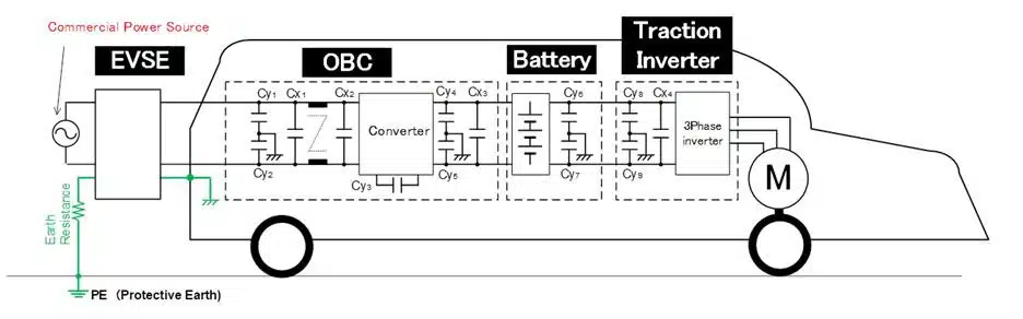
Figure 1 (below) shows the use of safety capacitors in an onboard charger. Two devices (CY1 and CY2) act as Y capacitors in the primary side of the circuit, two more (CY4 and CY5) play the same role in the secondary circuit, and two more pairs (CY6 and CY7) perform the same function for the battery (CY6 and CY7) and the traction inverter (CY8 and CY9). Capacitors CX1 ­– 4 perform smoothing functions throughout the powertrain.

The high-voltage design challenge

Battery packs are made up of hundreds of individual cells, each producing around 4V when fully charged, wired in series to produce the requisite pack operating voltage. It’s the design of the pack, and the battery management system (BMS) that controls how each cell in it is charged and discharged, which enables faster charging. The other gating factor for faster charging is the availability of key components, such as safety capacitors, which have high enough operating-voltage ratings to implement it and meet automotive safety requirements.

Evolution of the necessary components is well underway in the semiconductor industry, with the development of 1200V silicon IGBTs and the introduction of silicon carbide MOSFETs. However, all these parts have breakdown limits which, if reached, can cause the device to fail unpredictably. Breakdown voltages are usually specified at operating temperatures of 25°C but may be reduced at lower temperatures. Component developers must also consider measurement-error margins because it is likely that the safety of their components will be tested at considerably more than their rated operating voltages for short periods.

Passive components makers also need to minimize the ageing of their components in service, avoid the ingress of moisture in the harsh operating conditions of a car, and avoid ‘creep’, that is the tendency for currents to stray across component casings and printed circuit boards (PCBs) when very high voltages are present.

An example: the capacitor

Capacitor makers are already having to contend with these issues. The powertrains of EVs need a variety of safety features, including safety capacitors to act as common-mode filters and circuit isolators. These devices, such as the EVA series from Murata, are either used across power lines (so-called class X applications) where a failure would not cause an electric shock, or between the line and the vehicle’s chassis (class Y) in a configuration that, in the event of a short circuit, could cause a fire or electric shock.

Fig 1: Safety capacitor usage in an EV onboard charger circuit

Figure 1. shows the use of safety capacitors in an onboard charger, with two devices (CY1 and CY2) acting as Y capacitors in the primary side of the circuit, two more (CY4 and CY5) taking the same role in the secondary, a two more pairs (CY6 and CY7) performing the same function for the battery (CY6 and CY7) and the traction inverter (CY8 and CY9). Capacitors CX1 ­– 4 perform smoothing functions throughout the powertrain.

EV makers currently use multiple lower-voltage capacitors – often bulky, through-hole mounted film capacitors – to cope with the very high operating voltages of the latest EVs.  These devices work but need special handling during manufacture. The use of multiple devices to emulate the characteristics of a single higher-voltage device can also lead to higher equivalent series resistance and equivalent series inductance for the composite device than for a monolithic solution, undermining their ability to suppress electrical noise.
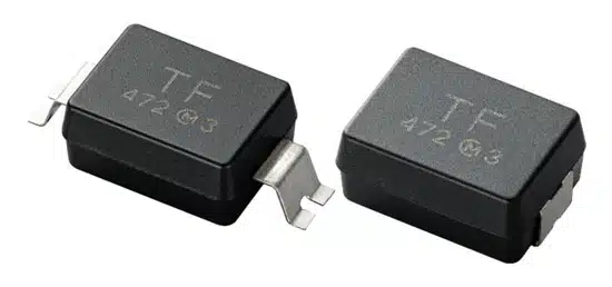
Figure 2: EVA packages with external and internal bending.

To address these issues, Murata has developed a range of surface-mountable multilayer ceramic capacitors (MLCCs) with peak DC operating voltages of 1500V and peak AC operating voltages of up to 305Vrms. The EVA capacitors offer a creep distance of 6 and 10mm, making arcing less likely than in other devices with creep distances of just 4mm. Using Murata’s EVA parts also saves PCB area and assembly costs and should improve manufacturing yields.

The high DC and AC operating voltages of the parts give them the headroom to work in today’s EV drivetrains, and to take a role in an emerging class of vehicles that are using 800V DC and 900V DC battery packs to reduce resistive losses.

 Figure 2 shows two different packages of the EVA type, with outside bending type (10mm creepage) and inside bending type (6mm creepage).

The EVA devices join Murata’s range of safety capacitors, which includes the DE6 parts offered in a through-hole mounting package and the surface-mountable KCA parts, which have a creepage distance of 4mm. Although the EVA parts are longer to accommodate the increased creepage distance, they retain the mechanical strength of the KCA parts because they have metal terminations and an internal design that focuses on electrical strength.

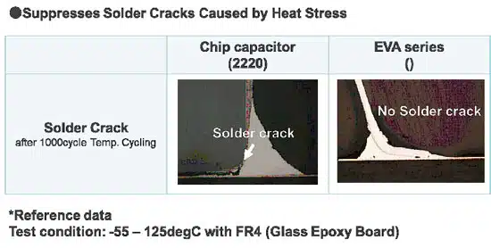
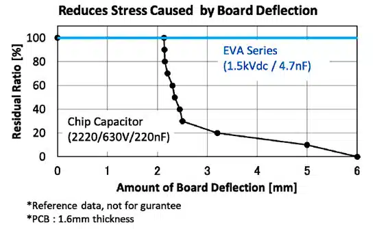
The result is a range of parts that will withstand cracks within the device due to PCB flexure and will resist solder cracking between the device and the board more effectively than devices without metal terminations (See Figure 3 and Figure 4).   
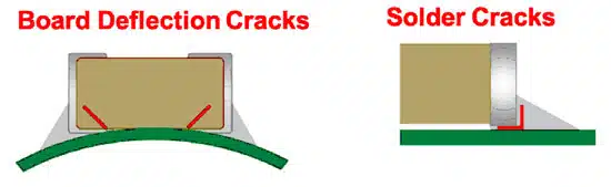
Figure 3: Common forms of mechanical failure for MLCCs due to PCB flexure
Figure 5: These cross-sections show how the EVA series capacitors reduce the effects of thermal cycling on critical solder joints.
Figure 4: Comparing the robustness of ceramic capacitors with and without metal terminations.

Meeting standards

Parts for use in automotive applications must meet the industry’s AEC-Q200 quality standards, conform to the requirements of RoHS legislation, offer operating temperatures of up to 125C, and show they can deal with moisture effectively over the long term. The JEDEC standards body defines Moisture Sensitivity Levels at which a component could be damaged during reflow soldering due to the expansion of moisture trapped within the part.

Parts that need to have the lowest risk of this happening must be baked for a fixed period to dry them out, and then supplied on a tape reel in an aluminium pack with a desiccant. The EVA parts will meet MSL3, which means that they have been tested to show that they will not crack under MSL2 conditions following the JEDEC standard. Murata will also recommend the right temperature and humidity for the parts’ storage.

Conclusion

The rapid development of EVs is completely reshaping how we think about vehicle design. To keep up with the feverish pace of EV development, vehicle makers are having to adapt existing technologies, techniques, and components to their needs, while suppliers rush to produce parts optimised for these new use cases.

Murata is already well advanced with product development for the EV market, as shown by the introduction of the EVA MLCCs. It will be interesting to see how EV designs evolve once the industry moves from using the components it can get to using the components it wants – like the Murata EVA MLCCs.
Related

Source: Murata

Recent Posts

Stackpole RPCQ thick-film chip resistors in rectangular surface-mount packages with end terminations

Stackpole Releases Pulse-Withstanding Chip Resistors up to 4 W

12.11.2026
11
Würth Elektronik ABC of Thermal Management textbook

Würth Elektronik Launches ABC of Thermal Management Guide

11.11.2026
26
Schematic of six-arm nitrene crosslinker joining PEI polymer chains in a free-standing dielectric film.

Crosslinked PEI Film Capacitor Dielectrics Reach 6 J/cm³ at 200°C

11.11.2026
24
Conceptual illustration of Peak Nano NanoPlex HDC capacitor dielectric film rolls beside a cast-film production line

Peak Nano Scales NanoPlex HDC Capacitor Film Production 20-Fold

10.11.2026
28
Reference tantalum capacitor anode characterization, tantalum anode modeling, process selection and life-test verification.

Tantalum Anode Design Combines Structural Benchmarks and Modeling

9.11.2026
24
Illustration of a thin-film capacitor stack with TiN electrodes and an ultrathin hafnium zirconium oxide ferroelectric layer on silicon

Sub-Volt Ferroelectric HZO Capacitor Pairs Speed and Endurance

6.11.2026
24
Cut-open lithium-ion capacitor pouch cell showing stacked carbon electrodes and separators, with vials of carbon powder

Lithium-Ion Capacitor Review Backs Hard Carbon//AC Pairing

6.11.2026
25
Rack power shelf in an AI data center with film DC-link capacitors, a supercapacitor bank and a converter board

800 VDC AI Data Centers Reshape Capacitor Demand for 2027

6.11.2026
89
YAGEO PMT6397 push-pull transformer with a segmented toroidal winding and surface-mount terminals

YAGEO Releases Push-Pull Transformers for Isolated 3 W Supplies

5.11.2026
20

Upcoming Events

Nov 24
16:00 - 17:00 CET

Select the Correct Components for Your DC/DC Converter

Dec 1
16:00 - 17:00 CET

Developing low-noise mixed-signal systems

Dec 8
16:00 - 17:00 CET

WE-CCMF: Design Principles, Layout Guidelines and Measurement Results for High-Speed EMI Filtering

View Calendar

Popular Posts

  • Buck Converter Design and Calculation

    0 shares
    Share 0 Tweet 0
  • September 2026 Interconnect, Passives and Electromechanical Components Market Insights

    0 shares
    Share 0 Tweet 0
  • Boost Converter Design and Calculation

    0 shares
    Share 0 Tweet 0
  • Capacitor Charging and Discharging

    0 shares
    Share 0 Tweet 0
  • LLC Resonant Converter Design and Calculation

    0 shares
    Share 0 Tweet 0
  • RF Connector Types: How To Choose the Right One

    0 shares
    Share 0 Tweet 0
  • Passive Low Pass Filters: Fundamentals and EMI Design

    0 shares
    Share 0 Tweet 0
  • Flyback Converter Design and Calculation

    0 shares
    Share 0 Tweet 0
  • MLCC and Ceramic Capacitors

    0 shares
    Share 0 Tweet 0
  • Audio Capacitors: Choosing Capacitors for Crossover Circuits

    0 shares
    Share 0 Tweet 0

Newsletter Subscription


Passive Components Blog

© 2015–2026
All rights reserved

  • Home
  • Privacy Policy
  • EPCI Membership & Advertisement
  • About

No Result
View All Result
  • Home
  • Knowledge Blog
  • Dossiers
  • PCNS

© 2015–2026
All rights reserved