• Latest
  • Trending
  • All
  • Capacitors
  • Resistors
  • Inductors
  • Filters
  • Fuses
  • Non-linear Passives
  • Applications
  • Integrated Passives
  • Oscillators
  • Passive Sensors
  • New Technologies
  • Aerospace & Defence
  • Automotive
  • Industrial
  • Market & Supply Chain
  • Medical
  • RF & Microwave
  • Telecommunication

Solenoids and Transformers

17.1.2023

Practical LLC Transformer Design Methodology

31.3.2023

Practical Measurement of Crystal Circuits

31.3.2023

March 2023 ECIA NA Electronic Components Sales Misses Expectations

31.3.2023

4th PCNS Call for Abstracts Extended !

30.3.2023

Würth Elektronik Presents New Series of DC-Link Film Capacitors

30.3.2023

Vishay Increases Anti-Surge Thick Film 0805 Power Resistor Performance with 0.5 W Power Rating

29.3.2023
  • Home
  • Privacy Policy
  • EPCI Membership & Advertisement
  • About
No Result
View All Result
NEWSLETTER
Passive Components Blog
  • Home
  • NewsFilter
    • All
    • Aerospace & Defence
    • Antenna
    • Applications
    • Automotive
    • Capacitors
    • Circuit Protection Devices
    • Filters
    • Fuses
    • Inductors
    • Industrial
    • Integrated Passives
    • Market & Supply Chain
    • Medical
    • New Materials & Supply
    • New Technologies
    • Non-linear Passives
    • Oscillators
    • Passive Sensors
    • Resistors
    • RF & Microwave
    • Telecommunication

    Practical LLC Transformer Design Methodology

    Practical Measurement of Crystal Circuits

    March 2023 ECIA NA Electronic Components Sales Misses Expectations

    4th PCNS Call for Abstracts Extended !

    Würth Elektronik Presents New Series of DC-Link Film Capacitors

    Vishay Increases Anti-Surge Thick Film 0805 Power Resistor Performance with 0.5 W Power Rating

    Q&A Update on Aluminum Capacitor Technology with Industry Highest Energy Density >5J/cc Available for Acquisition

    Designing with High Voltage Resistors: 10 Top Tips for Success

    API Delevan Introduces 0402 and 0603 Small High Reliability Space SMD Inductors

    Trending Tags

    • Ripple Current
    • RF
    • Leakage Current
    • Tantalum vs Ceramic
    • Snubber
    • Low ESR
    • Feedthrough
    • Derating
    • Dielectric Constant
    • New Products
    • Market Reports
  • VideoFilter
    • All
    • Antenna videos
    • Capacitor videos
    • Filter videos
    • Fuse videos
    • Inductor videos
    • Non-linear passives videos
    • Oscillator videos
    • Passive sensors videos
    • Resistor videos
    • Sensors

    Practical LLC Transformer Design Methodology

    Practical Measurement of Crystal Circuits

    Investigating Modeling Techniques of Class II Ceramic Capacitors Losses for High Voltage and Current Applications

    Understanding Basics of Current Sense Resistors

    What Decoupling Capacitor Value To Use And Where To Place Them

    How to Measure Rated Current on Power Inductors

    LTspice Simulation of a Spark-Gap Circuit Protection Surge Arrester

    Approximate Inductor Design Using Two Alternative Cores

    1kW Phase Shift Full Bridge Converter Design and Simulation

    Trending Tags

    • Capacitors explained
    • Inductors explained
    • Resistors explained
    • Filters explained
    • Application Video Guidelines
    • EMC
    • New Products
    • Ripple Current
    • Simulation
    • Tantalum vs Ceramic
  • Knowledge Blog
  • Suppliers
    • Preferred Suppliers
    • Who is Who
  • Events
No Result
View All Result
Passive Components Blog
No Result
View All Result

Solenoids and Transformers

17.1.2023
Reading Time: 12 mins read
0 0
0
SHARES
1.2k
VIEWS

This article explains the basic functionality and equations of transformer and solenoid.

Transformers

What is a transformer ?

RelatedPosts

Transformer Topologies in Power Converters

Introduction to RFID Technology

Failure Analysis of Capacitors and Inductors

A transformer is a device that transfers electric energy from one alternating-current circuit to one or more other circuits, either increasing (stepping up) or reducing (stepping down) the voltage.A transformer consists of at least two windings, with the winding turns NP on the primary side and NS on the secondary side.

For the sake of simplicity, we will look at an ideal transformer with a turns ratio of 1 : 1.

In a first step, we will look at a transformer with an open secondary winding NS (Figure 1.). A UP voltage pulse is created at winding NP. Due to the inductance of the winding, this pulse generates a linearly progressive current IP.

The following applies:

transformer voltage pulse eq. [1]
Figure 1. Principle of a transformer with zero load. This ideal transformer is wound as a bifilar so as to ignore parasitic effects.

Winding NS also wraps around this magnetic flux. Changing the magnetic flux creates voltage.

induced voltage in transformer by magnetic flux [2]


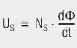
If you solve both equations after changing the voltage and then equate them, you will get the following for the voltage transformation expressed by eq. [3].

voltage transformation eq. [3]

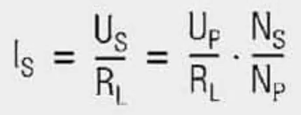
Current does not flow in winding NS because the winding is open. If we now connect winding NS to a load resistor RL (Figure 2.), the voltage induced in NS generates a current flow through the load resistor:

current through transformer eq. [4]
Figure 2. The same transformer as in Figure 1. but with a load

The primary current now consists of the transformed secondary current and the linearly progressive magnetisation current that is already available without load.

transformer primary current eq. [5]

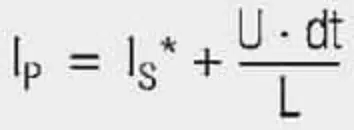
IS* Secondary current transformed on the primary side

As no power can be generated, the transformed power is the same as the primary power put into the system. If the magnetisation current is disregarded, the following applies:


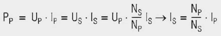
Currents are thus transformed in the reversed direction as voltage. The following also applies:


Resistances are thus transformed with the transformation ratio squared. This also applies to inductances, capacitances and impedances. So the magnetising current is not transferred to the secondary side. It is required to generate the magnetic field. The aim of the transformer design must therefore be to keep the magnetizing current as small as possible.

There are two possibilities here:

  • Insertion of a highly permeable core to increase the primary inductance. This causes the magnetizing current to rise less steeply and is therefore smaller (Figure 3.).
Figure 3. Magnetizing current of a transformer with and without a highly permeable core
  • Shorter voltage pulses with higher frequency are generated, as the rise in current stops at the end of the voltage pulse and starts again at the original point for the next pulse (Figure 4.).
Figure 4. Magnetizing current for a transformer at different driving frequencies

Parasitic effects
In reality, there are other factors that affect the behavior of transformers. The most important ones are:

Figure 5. Long solenoid concentric coil
  • Leakage inductance
  • Coupling capacitance (capacitance between windings)
  • Winding capacitance (capacitance within a winding)

Leakage inductance
Looking at two windings, we see that the entire flux is not coupled to the other winding. A part of the streamlines of the magnetic field closes outside of the other winding. This part of the inductance is called “leakage inductance.” To understand how to minimize leakage inductance, you must know the parameters that influence it.

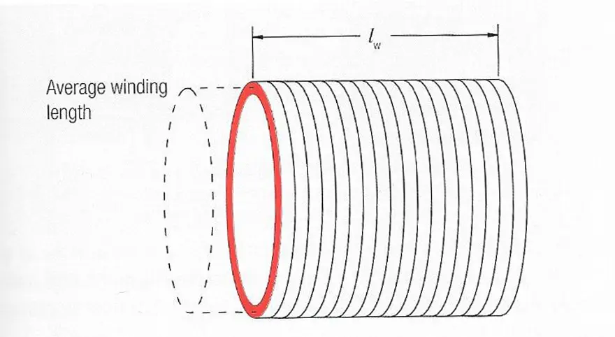
If you look at a long concentric coil (Figure 5.), its inductance results from:

concentric coil inductance eq. [5]


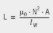
lW Length of the coil
N Winding turns
A Cross section of the coil

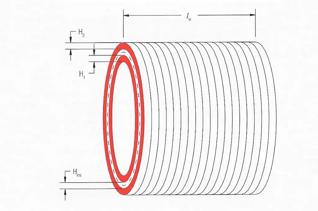
If a second winding is wound on top of it (Figure 6.), the leakage inductance results from eq. [6]

leakage inductance on second winding [6]
Figure 6. Long solenoid concentric coil with second winding

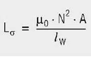
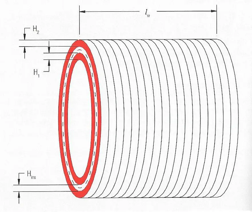
Where A here is the surface between the two windings. It can be calculated using:

surface between two windings eq. [7]

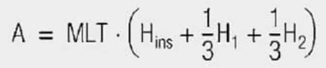
MLT Mean length of turn
Hins Distance between the windings (isolation)
H1, H2 Winding height of windings 1 and 2

Figure 7. Different transformer winding structures

Coupling Capacitance

You can picture the coupling capacitance between the two windings as plate capacitor between the two windings. From this it follows that you can reduce this capacitance either by increasing the distance or reducing the surface. Both directly increase leakage inductance.

Winding Capacitance

Each winding builds up winding capacitance because they are isolated from each other and rest on different potential. This capacitance increases with the number of layers that are required within a winding. It can be reduced by means of various winding technologies, e.g. Z-wind (wire is returned after each layer).

Solenoids

Derived from two Greek words: Solen (pipe) and Eidos (coil), the solenoid is a type of an electromagnetic device that converts electrical energy into mechanical energy. It is generally made by tightly wounding wires in a helix shape around a piece of metal. Whenever an electric current passes through it, a magnetic field is created.

Working Principle

A solenoid works on electromagnetism and electromagnetic force. It consists of a round cylindrical coil that has several number of wire turns, and a metal rod inside the coil that is free to move. When an electric current is provided to the coil, a magnetic field is generated due to which the metal core or rod inside the coil gets attracted due to towards the direction where the magnetic flux is high. This electromagnetic effect in a solenoid enables any connected plunger or armature to move as per our need. 

To increase the magnetic force produced in a solenoid coil, we will have to increase the number of turns, N and the current, I.

Types Of Solenoid

DC-C Frame Solenoid
DC-C Frame Solenoid

AC Laminated Solenoid

It has a very high initial attracting force and very short closing time. It is made with a laminated metal or insulated thin sheets that are individually ,assembled.
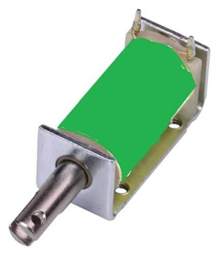
DC-D Frame Solenoid

DC-C Frame Solenoid

As its name states, this solenoid is constructed in such a way that it has a letter ‘C’ like frame cover around the coil. This type is widely used in gaming machines.
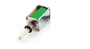
DC-D Frame Solenoid

As its name says, this solenoid has a coil that is covered by two ‘D’ frames on two sides. This types is generally used in AC power applications.

Linear Solenoid

Linear Solenoid
Linear Solenoid

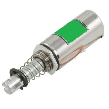
This type of solenoid has a freely movable steel or iron rod called plunger inside a round cylindrical shaped coil. The iron rod is allowed to freely move in or out of the cylindrical coil depending on the current applied.

Rotary Solenoid

It is a special type of solenoid where the magnetic force is converted into a rotational force or a rotary motion. It consists of an armature core mounted on a flat disk.
When a current is provided, the armature gets attracted towards the stator and the flat disk rotates.

Applications

Solenoid Valve

Solenoid Valve
Solenoid Valve

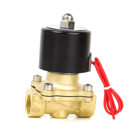
The solenoid valve is a simple device in which a solenoid is used for controlling and regulating the flow of fluid. It has a coil with free movable plunger or an iron rod with a spring inside it. When we energise the coil, the plunger moves from its position due to magnetic attraction and when we cut the power to coil, the plunger comes back to its original position with the help of a spring. As soon as the plunger comes in the path of the flowing fluid, its flow stops.
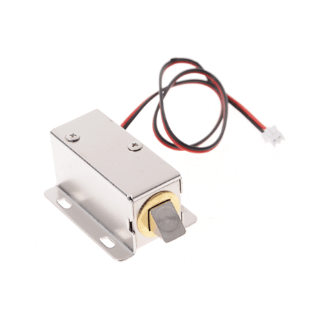
Solenoid Lock
Solenoid Lock

Solenoid Lock

Here we use the movement of solenoid plunger for the locking and unlocking mechanism. These solenoid locks are widely used in electronic and biometric password-based locks. It consists of a strong metal plunger that can move. When the coil gets magnetised due to an electric field, the plunger moves to perform the lock and unlock mechanism.

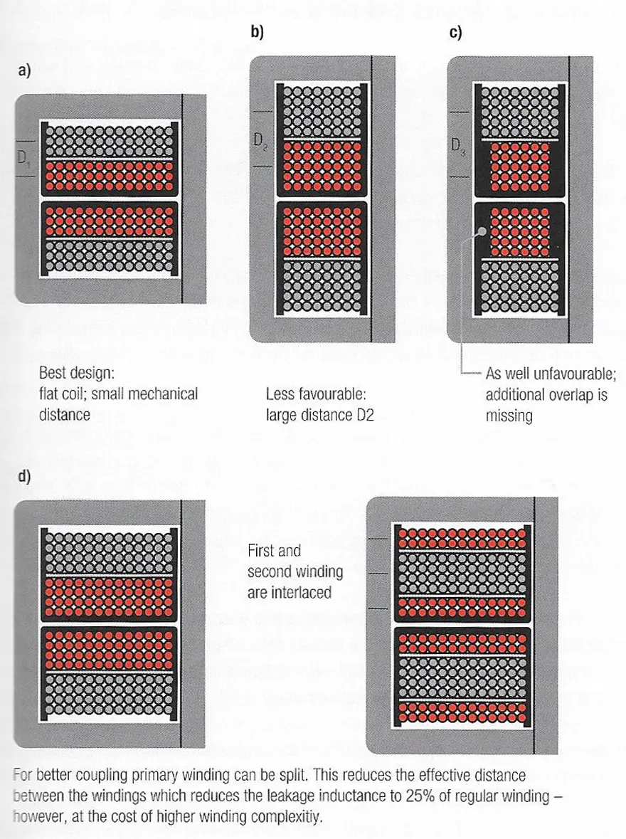
The leakage inductance is thus independent of core material and air gap. To minimize leakage inductance you must either increase the length of the coil (broad windings) or reduce the distance between the windings (e.g. bifilar wind).

Figure 7. shows various more or less ideal winding constructions. With existing geometry the most commonly used means is a sandwich construction (Figure 7.d), in which the secondary winding is wound between the primary winding that is divided into two halves. This doubles the length of the winding.

Related Posts

Inductors

Practical LLC Transformer Design Methodology

31.3.2023
1
Oscillators

Practical Measurement of Crystal Circuits

31.3.2023
3
Market & Supply Chain

March 2023 ECIA NA Electronic Components Sales Misses Expectations

31.3.2023
2

Upcoming Events

Apr 3
April 3 @ 12:00 - April 4 @ 14:00 CEST

Microelectronic Packaging Failure Modes and Analysis

Apr 5
11:00 - 12:00 CEST

Plugging – Filling – Tenting; WE PCB Webinar

Apr 6
April 6 @ 12:00 - April 7 @ 14:00 EDT

Space and Military Standards for Hybrids and RF Microwave Modules

View Calendar

Popular Posts

  • What is a Dielectric Constant of Plastic Materials ?

    4 shares
    Share 4 Tweet 0
  • Ripple Current and its Effects on the Performance of Capacitors

    3 shares
    Share 3 Tweet 0
  • Capacitor Selection for Coupling and Decoupling Applications

    28 shares
    Share 28 Tweet 0
  • Why Low ESR Matters in Capacitor Design

    0 shares
    Share 0 Tweet 0
  • Leakage Current Characteristics of Capacitors

    0 shares
    Share 0 Tweet 0
  • Capacitor Losses (ESR, IMP, DF, Q), Series or Parallel Eq. Circuit ?

    0 shares
    Share 0 Tweet 0
  • How to Choose the Right Inductor for DC-DC Buck Applications

    0 shares
    Share 0 Tweet 0
  • Understanding High-Precision Resistor Temperature Coefficient of Resistance

    0 shares
    Share 0 Tweet 0

Newsletter Subscription


PCNS Call for Papers !

Archive

2022
2021
2020
2019
2018
2017

Symposium

Passive Components Networking Symposium

Passives e-Learning

Knowledge Blog

  • Home
  • Privacy Policy
  • EPCI Membership & Advertisement
  • About

© EPCI - Premium Passive Components Educational and Information Site

No Result
View All Result
  • Home
  • News
  • Video
  • Knowledge Blog
  • Preferred Suppliers
  • Events

© EPCI - Premium Passive Components Educational and Information Site

Welcome Back!

Login to your account below

Forgotten Password?

Retrieve your password

Please enter your username or email address to reset your password.

Log In
This website uses cookies. By continuing to use this website you are giving consent to cookies being used. Visit our Privacy and Cookie Policy.