High frequency Helmholtz RF coils are often used to generate uniform but time varying high frequency magnetic field for a number of applications such magnetic field susceptibility, calibration, and scientific experiment.
A high frequency Helmholtz coil driver is needed to generate the required magnetic field. Because the magnetic field density is proportional to electrical current, to generate high magnetic field, high current is needed. However, at high frequency the coils impedance is also became high impedance.
For a given driver voltage amplitude, the coil current is inversely proportional to the coil impedance. Therefore the two opposing factors that affect magnetic field are current and frequency. Achieving high frequency magnetic field is very difficult. This article discussed three techniques to produce high magnetic field for high frequency Helmholtz coils.
Key Takeaways
- Helmholtz coils create uniform magnetic fields using two identical coils driven by the same current.
- Generating high frequency magnetic fields is challenging due to the coil’s increasing impedance with frequency.
- Three methods to drive Helmholtz coils include direct drive, series resonant, and current-amplified resonant methods.
- The current-amplified resonant method effectively doubles coil current at resonance, enhancing magnetic field strength.
- Accurate design and measurement are crucial for achieving the desired magnetic field in sensitive applications.
High Frequency Helmholtz Coils Basic
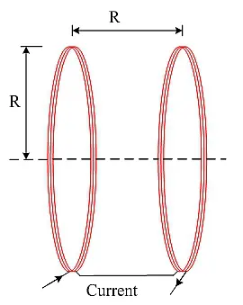
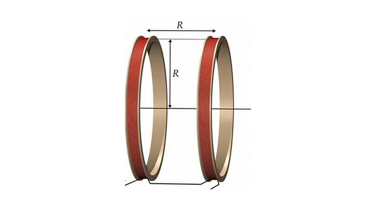
Helmholtz coils, named after the German physicist Hermann von Helmholtz, is consisted of two identical electromagnetic coils place in parallel and aligned their centers in the same axis like a mirror image as shown in Figure 1. When electrical current pass through the high frequency Helmholtz coils in the same direction, it creates a highly uniform magnetic field in a 3-dimension volume of space inside the coils. These Helmholtz coils are often used for cancel background (earth’s) magnetic field, measurements and calibration, and magnetic field for susceptibility testing of electronic equipment.
Helmholtz coil principle
A Helmholtz coil set consists of two identical circular coils, separated by a distance equal to their radius and driven with the same current in the same direction.
This geometry produces a highly uniform magnetic field in a central volume whose diameter is roughly half the coil radius and whose length is about half the coil spacing.
By arranging one, two, or three orthogonal coil pairs, it is possible to generate static or time‑varying magnetic fields in any direction within this central region.
passive-components
Helmholtz Coils Design and Construction
High frequency Helmholtz coils are constructed by two coils. Because the two magnetic coils are designed to be identical, uniform magnetic field is achieved when the coil radius is equal to the separation distance. The two coils are connected in series such that identical current feeding both of them creates two identical magnetic fields. The two added fields achieved uniform magnetic field in a cylindrical volume of space in the center between the two parallel coils.
This cylindrical-shaped volume space uniform field is approximately equal to 25% of coil radius (R) and a length equal to 50% of the spacing between the two coils. High frequency Helmholtz coils are available in 1, 2, or 3 axes. Multiple axis magnetic coils generate magnetic fields in any direction in the three dimensions space inside the Helmholtz pair. The most common high frequency Helmholtz coils are circular. Square Helmholtz coils are also commonly available.
Design considerations
- Coil radius and spacing: Use spacing equal to radius for best field uniformity; small deviations mainly affect the uniformity volume, not the center field value.
- Wire selection: Choose wire gauge such that current density stays within thermal limits at the highest duty cycle and frequency; at hundreds of kHz to MHz, skin and proximity effects increase the effective AC resistance over the DC resistance.
- Mechanical support: Use rigid, low‑loss formers (e.g. plastic or non‑magnetic composites) to keep coil alignment and spacing constant under thermal expansion.
- Cooling: For continuous high‑field operation, consider forced air or intermittent duty, because copper losses scale with both current and AC resistance.
Helmholtz Coils Magnetic Field Calculation
Each Helmholtz coil is constructed by loops of electrical (copper) wires. When electrical current is passing through it, magnetic field is generated. The magnetic field density is proportional to current. The Helmholtz coils magnetic field equation is given below.
From Equation 1, smaller radius coil generates higher magnetic field density. Also the more number of turns in each coil the stronger the magnetic field.
Design example – required field and current
As an example, assume a Helmholtz pair with radius R = 0.1 m, N = 100 turns per coil, and a target field of B = 1 mT at the center.
Rearranging Equation‑1 gives the required coil current; inserting these values shows that the needed current is on the order of amperes, which must then be checked against allowable copper loss and driver capability.
The same current is used in the following sections to estimate coil impedance, drive voltage and capacitor ratings for the three drive methods.
High Frequency Helmholtz Coils Model
Helmholtz magnetic field is generated either using AC or DC current. Most Helmholtz coils applications are static (constant) magnetic field using DC current. Some applications such scientific experiments required non-static magnetic fields at high frequency (kHz to MHz). This article is mainly discussing high-frequency Helmholtz coils.
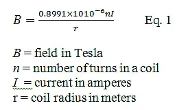
A pair of high frequency coils can be model as shown in Figure 2. Each coil can be modeled as a parasitic resistor in series with an ideal inductor. The parasitic resistor resistance is generally small. For most high frequency Helmholtz coils application where the testing frequency is well below the self-resonant frequency, this model is sufficient.
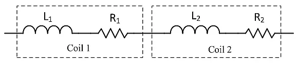
If the Helmholtz coil operating frequency is close enough to its self-resonant frequency, the circuit model must also include its parasitic capacitances (CP1 and CP2). The parasitic capacitors are parallel to each inductor and resistor in series as shown in Figure 3.
The parasitic capacitance and inductance formed a self-resonant frequency. Although the coils are designed to be as closely match as possible, but some small variations between them are expected. Each coil has its own series resistance and parasitic capacitance. The parasitic capacitance and the coil inductance formed a self-resonant frequency.
At high frequency, the coil’s effective resistance can be significantly higher than its DC resistance due to skin and proximity effects in the winding. For accurate loss and voltage calculations near the self‑resonant frequency, designers should either measure the complex impedance with an LCR meter or use simulation tools that include frequency‑dependent copper losses and parasitic capacitances.
High Frequency Helmholtz Coils Connections
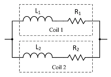
High frequency Helmholtz coils may be connected in series (Figure 2) or in parallel as shown in Figure 4. Series connection allows the same electrical current flow through the two magnetic coils. Generally series connection enables the highest current and thus highest magnetic field. However, because two coils are in series, the total impedance is also double. Higher impedance may require higher driver amplifier voltage. If used resonant techniques described below, the impedance is reduced.
The advantage of parallel Helmholtz coil connection is lower impedance. In fact the impedance is cut in half, but the current is also cut in half (current is split into two). Thus lower the magnetic field. Parallel connection is acceptable if the required magnetic field density is achieved at half the current and low impedance is required such as the case of low-voltage amplifier driver. More details on Helmholtz coil impedance below in the Direct Drive Method section.
| Aspect | Series coils + Direct drive | Series coils + Series resonance | Series coils + Current‑amplified resonance |
|---|---|---|---|
| Typical frequency range | Low kHz, low L or low B | Up to hundreds kHz / low MHz | Similar to series resonance, optimized for higher B |
| Driver requirement | High current, moderate voltage amplifier | Lower voltage at resonance, current set by R | Same amplifier current, but coil current ≈ 2× source |
| Impedance seen by driver | Inductive, rising with f (jωL) | Mostly resistive near f₀, reactance cancelled | Mostly resistive near f₀, ≈ 4× coil resistance |
| Magnetic field capability | Limited at high f due to voltage limit | High B at fixed resonance frequency | Highest B for given amplifier current |
| Frequency agility | Wideband | Narrowband around resonance, C must be re‑tuned | Narrowband, both capacitors linked to frequency |
| Complexity | Lowest | Moderate (one capacitor, high voltage rating) | Highest (two capacitors, tuning procedure) |
| Typical use cases | Simple LF tests, calibration | High‑field susceptibility tests, RF experiments | Maximum field density in limited volume |
Driving High Frequency Helmholtz Coils
There are three ways to produce high frequency AC magnetic field. The first method is direct drive method. This method is the simplest way to produce magnetic field for testing. It is very easy to vary the frequency and magnetic field under test. The second method is series-resonant method. This method is a powerful way to produce high magnetic field and very high frequency in the order hundreds kHz or even MHz. The third way is using a new current-amplified resonant method. This method generates the highest magnetic field density. The below sections will describe each method.
Direct Drive Method
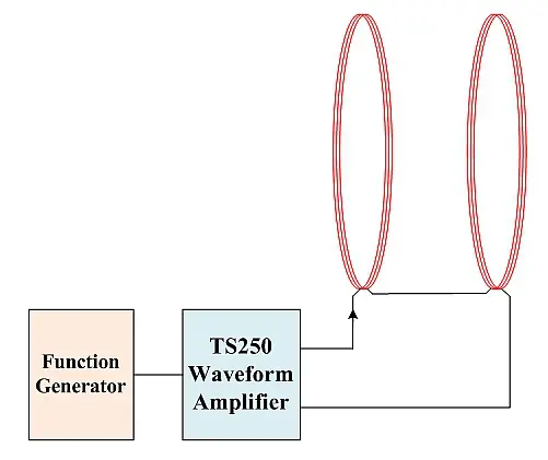
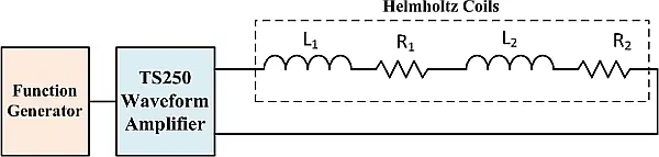
If the experiment is low frequency or the coils are low inductance or both, the Helmholtz coils may be driven directly using a waveform amplifier driver such as the TS250 Waveform Amplifier from Accel Instruments. Because of low frequency or low inductance, the coil’s impedance is low enough it can be driven by an amplifier directly as shown in Figure 5 and Figure 6.
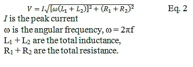
Use the Equation-1 to calculate the coil current for a desired magnetic field. Then use Equation-2 to calculate the maximum voltage is needed. Note the small parasitic resistance is ignored. The maximum voltage is when the current and frequency are both at maximum. The next step is to drive the Helmholtz coils with a high-current and high-frequency amplifier driver such as the TS250 function generator amplifier.
Series Resonant Method
If the generated magnetic field is high frequency, Helmholtz coils impedance increases with frequency (Z = jwL). At high frequency the coil impedance is very high such that high voltage is needed to drive high current through the coil. For example, at 200 kHz the impedance of a 2mH coil will be 2512 ohm. If you drive the coil with a 40V for example, you would get about 16mA (40V/2512 ohm = 16mA). For most applications, this is not enough current to produce enough magnetic field. For high magnetic field applications, higher current through the coil is desired. To drive a 2A high-current through the coil, 5024V is needed! It is difficult to generate 5kV at 200kHz.
To achieve high-current and high-frequency electromagnetic field, series resonant technique can be recommended.
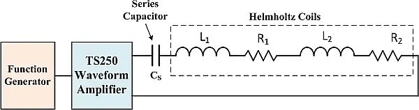
To operate the high frequency Helmholtz coils in resonance mode, a series capacitor is added as shown in Figure 7. The series capacitor impedance has an opposite polarity than the inductor. Thus the capacitor is acting as an impedance cancelation device. It reduces the total impedance. At resonance the capacitor reactance (imaginary portion of the impedance) is completely cancels the inductor reactance. That is the inductor and capacitor reactance are equal magnitude but opposite polarity.
Only the inductor’s parasitic resistance remained. With only resistance remained, the function generator amplifier (TS250) can drive high current through the Helmholtz coils (LCR circuit) even at high frequency. This method enables the signal amplifier to drive high current through the high frequency coils, but it can only operate at a very narrow frequency range near resonance. The disadvantage of resonant technique is that you need to change the capacitance when you change the frequency.
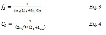
The series-resonant frequency of the Helmholtz coils is given in Equation-3. The series capacitance, CS, is calculated using Equation-4. The voltage across the series capacitor is given in Equation-2 above. At high frequency and high current, the voltage could be in the thousands volts. For example, at 200kHz and 1A current though a 2mH high frequency Helmholtz coils, the voltage across the capacitor is 2512V! The capacitor must be rated for at least that voltage.
Caution: Potential Electrical Shock
High-current Helmholtz (electromagnetic) coils discussed above can store enough energy to become an electrical shock hazard. Make sure all electrical connections are insulated with high-voltage insulators. Wires must be rated for voltages rating discussed above. Always disable the waveform amplifier output before connecting or disconnecting the coil and capacitor.
Current-Amplified Resonant Method
Another resonant that is even more powerful than the series resonant is called the current-amplifier resonant. This newly discovered resonant can boost the Helmholtz coils current by a factor of two. That is the coil current is twice the source amplifier driver current. Hence the resonant is magnifying current and the magnetic field. Detail information of this newly discovered resonant can be found in the application note High Frequency Magnetic Field Generator.
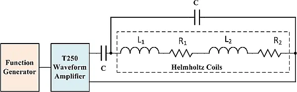
Figure 8 shows the high frequency Helmholtz coils connection using the current-amplified resonant. Two equal value capacitors are needed. One capacitor is connected in series with the coils, similar to the series resonant discussed above. A second resonant capacitor is connected in parallel with the two coils. This parallel capacitor is similar to the parasitic capacitors discussed above in the high frequency Helmholtz coils circuit models.
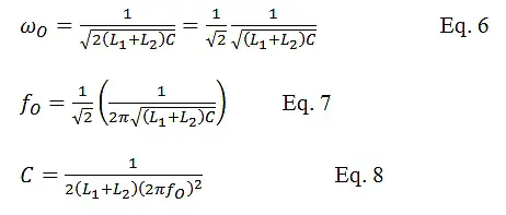
The resonant frequency is expressed in Equation-6. The two capacitor values are calculated in Equation-8. At resonant, the Helmholtz coils impedance is resistive and 4 times the coils parasitic resistance. It is desirable to design low resistance coils when used in the current-amplified resonant. Also keep in mind the magnetic coil’s AC resistance is higher than DC due to the skin-effect.
Practical implementation and measurement
- Field measurement: Magnetic field can be verified with calibrated Hall probes or search coils placed at the center and at several points in the intended uniform‑field volume.
- Uniformity check: Compare readings across the test volume; deviations indicate misalignment, incorrect spacing, or asymmetrical winding.
- Safety and EMC: Because high‑frequency, high‑current operation can develop kilovolt‑level capacitor voltages, all connections must use appropriate insulation, creepage and clearance, and the setup should be enclosed to minimize stray coupling into nearby equipment.
Conclusion
This article has reviewed the operating principles of Helmholtz coils and three practical methods for driving them at high frequency. Direct drive offers the simplest implementation and the widest frequency agility, but it is generally limited to lower frequencies or low‑inductance coils. Series‑resonant drive enables much higher coil current and magnetic field at a fixed frequency, at the cost of narrowband operation and high capacitor voltage stress.
The current‑amplified resonant method further increases the achievable magnetic field for a given amplifier current by effectively doubling the coil current at resonance, making it attractive where maximum field strength in a limited volume is required. Careful coil design, impedance characterization and field measurement are essential to ensure that the intended magnetic field is achieved safely and reproducibly in demanding RF and susceptibility test setups.
FAQ
A high frequency Helmholtz coil is a pair of identical coils separated by a distance equal to their radius and driven with the same AC current to generate a highly uniform, time‑varying magnetic field in the volume between them.
t high frequency the coil impedance increases with frequency, so much higher drive voltage is needed to maintain the same current, which limits the achievable magnetic field if no resonant techniques are used.
The three common methods are direct drive, series‑resonant drive, and current‑amplified resonant drive, each with different complexity, frequency range, and achievable magnetic field strength.
Direct drive is suitable for lower frequencies or low‑inductance coils where the coil impedance remains moderate, allowing a wide frequency range with a simple high‑current amplifier.
eries resonance cancels the inductive reactance with a series capacitor so the amplifier sees mainly resistance, enabling much higher current and magnetic field at a fixed resonance frequency.
By using both a series and a parallel capacitor, the current‑amplified resonant topology makes the coil current approximately twice the amplifier current at resonance, effectively boosting the magnetic field in the test volume.
You can measure the field using calibrated Hall probes or search coils at the center and several positions in the uniform‑field region, then compare readings to assess uniformity and alignment.
At resonance, especially with high current, capacitor voltages can reach kilovolt levels, so you must use appropriate insulation, creepage and clearance distances, shielded connections, and always disable the amplifier output before changing the setup.
How to drive a high frequency Helmholtz coil using series resonance
- Step 1 – Define target field and frequency
Set the required magnetic field at the coil center and the operating frequency range for your test or experiment, for example 1 mT at 200 kHz.
- Step 2 – Calculate required coil current
Use the Helmholtz field equation for your coil radius and number of turns to calculate the current needed to achieve the target field at the center.
- Step 3 – Measure coil inductance and resistance
Measure the coil pair in the intended series configuration with an LCR meter to obtain the inductance and effective resistance at the operating frequency.
- Step 4 – Choose and calculate the series capacitor
Select a suitable resonance frequency and calculate the required series capacitance so that the capacitor reactance cancels the inductive reactance of the coils at that frequency.
- Step 5 – Check capacitor voltage rating
Estimate the voltage across the series capacitor from the product of coil current and inductive reactance; choose a capacitor with sufficient voltage and current rating, often in the kilovolt range.
- Step 6 – Connect the amplifier, capacitor, and coils
Connect the waveform amplifier output in series with the capacitor and Helmholtz coil pair, ensuring correct polarity, short leads, and proper insulation for all high‑voltage nodes.
- Step 7 – Tune to resonance and verify current
Gradually increase the drive amplitude at the target frequency while monitoring coil current and voltage; fine‑tune frequency or capacitance so that the coil impedance appears mainly resistive and the desired current is reached.
- Step 8 – Measure and confirm the magnetic field
Use a Hall probe or search coil to measure the magnetic field in the test volume, verify uniformity at several points, and document the drive conditions that achieve the required field.
References:
- Accel Instruments Corp., “Magnetic Field Generator Uses New Resonant Circuit,” application note.
- Accel Instruments Corp., “Helmholtz Coil,” application note.