Passive Components Blog
No Result
View All Result
  • Home
  • NewsFilter
    • All
    • Aerospace & Defence
    • Antenna
    • Applications
    • Automotive
    • Capacitors
    • Circuit Protection Devices
    • electro-mechanical news
    • Filters
    • Fuses
    • Inductors
    • Industrial
    • Integrated Passives
    • inter-connect news
    • Market & Supply Chain
    • Market Insights
    • Medical
    • Modelling and Simulation
    • New Materials & Supply
    • New Technologies
    • Non-linear Passives
    • Oscillators
    • Passive Sensors News
    • Resistors
    • RF & Microwave
    • Telecommunication
    • Weekly Digest

    Panasonic Releases Relays for IEC 62955 Compliant Single‑Phase EV Wallboxes

    KYOCERA AVX Releases NTN Antenna Selection Guide Brochure

    Coilcraft Releases 0402 Ferrite-Core Wirewound Chip Inductors for RF and EMI Control

    DigiKey Releases Season Two of Sustainable Futures Series

    Using a Virtual Anode Thermal Model to Evaluate Miniaturization Risk in Tantalum Capacitors

    Bourns Introduced High-Current Coupled Inductor for 48 V Hybrid and IBC Converters

    Würth Elektronik Expands Nanocrystalline Cable Cores for Broadband EMI Suppression

    High‑Speed Supercapacitor Balancing for AI Data Center Power Systems

    Bourns Introduced Automotive TVS Diodes for Compact ESD Protection

    Trending Tags

    • Ripple Current
    • RF
    • Leakage Current
    • Tantalum vs Ceramic
    • Snubber
    • Low ESR
    • Feedthrough
    • Derating
    • Dielectric Constant
    • New Products
    • Market Reports
  • VideoFilter
    • All
    • Antenna videos
    • Capacitor videos
    • Circuit Protection Video
    • Filter videos
    • Fuse videos
    • Inductor videos
    • Inter-Connect Video
    • Non-linear passives videos
    • Oscillator videos
    • Passive sensors videos
    • Resistor videos

    EMC‑Compliant PCB and Connector Design Guidelines

    Why Isolated DC/DC Power Supplies Fail Late, Würth Elektronik Podcast

    Designing 800 V DC EMC Filters: Calculation, Simulation and Measurement

    Current Sense Transformer Datasheet and Design‑in Guide

    Designing a USB Type‑C Flyback Planar Transformer with Frenetic’s Planar Tool

    Magnetics Design in High‑Frequency GaN Converters

    Qi2 Wireless Charging: Inductors, Capacitors and EMC Filters

    Two‑capacitor paradox explained for engineers

    Capacitances of Nonlinear MLCCs: What Datasheets Don’t Tell You

    Trending Tags

    • Capacitors explained
    • Inductors explained
    • Resistors explained
    • Filters explained
    • Application Video Guidelines
    • EMC
    • New Products
    • Ripple Current
    • Simulation
    • Tantalum vs Ceramic
  • Knowledge Blog
  • DossiersNew
  • Suppliers
    • Who is Who
  • PCNS
    • PCNS 2025
    • PCNS 2023
    • PCNS 2021
    • PCNS 2019
    • PCNS 2017
  • Events
No Result
View All Result
Passive Components Blog
No Result
View All Result

How to Optimize Magnetizing Inductance for ZVS Zero Volt Switching

9.11.2023
Reading Time: 5 mins read
A A

This article based on Sotiris Zorbas, Power Εlectronics Εngineer Frenetic newsletter discusses optimisation of magnetic inductance for ZVS zero volt switching.

Our mission today is to understand how an LLC Converter achieves ZVS on the primary side.

RelatedPosts

Designing a USB Type‑C Flyback Planar Transformer with Frenetic’s Planar Tool

Designing a Custom Core Transformer for 10 kW LLC Data Center Power Stages

Magnetics Design in High‑Frequency GaN Converters

The zero-voltage switching in an LLC Converter is directly linked to the magnetizing inductance of the Transformer and the output parasitic capacitance Coss of the mosfets that form the full/half driving bridge.

Let’s start from an LTspice schematic as you can see in Figure 1.

I have used a simple trick for the Transformer model: I kept the series and magnetizing inductances separate and used an ideal Transformer utilizing high inductance perfectly coupled inductors.

That way, I could monitor the magnetizing current going through Lm (L4) and that going to L3, thus the load eventually. L7, L2 secondaries are sized at 1H/n^2, where n is the turns ratio.

Figure 1. An LLC Converter

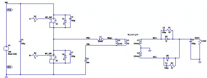
What else is important in that schematic?

Switches S2, S3 are working like on/off switches using the Rds_on of the selected mosfet each time. The important part is putting a couple of capacitors in parallel with these to model the output parasitic capacitance. That parameter can be found in the respective datasheets of the selected device. However, there is a trap here!

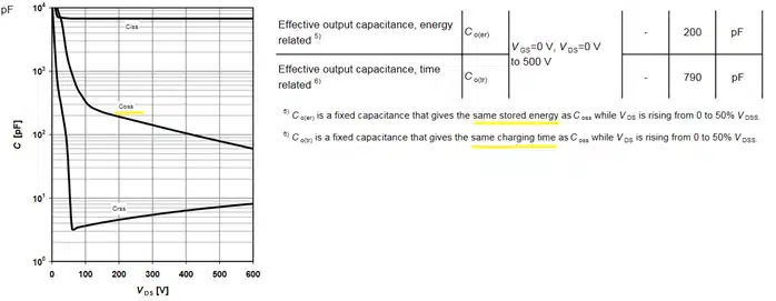
Is the output capacitance calculated based on time, or energy?

The output capacitance changes dynamically in mosfets when switching, ranging from a few picofarads to a few nanofarads, as the voltage on the drain-source pins drops from a high to a low potential. The manufacturer has constructed an artificial effective capacitor that either gives the same stored energy value or the same charging time.

Looking at Figure 2 helps to better understand what I’ve just described.

Figure 2.  IPW90R120C3 power mosfet Coss values

An example design – case study.

I have used the worked example in SLUA923 reference below, to help the reader. The specs are listed in Table 1.

The first thing when looking to achieve ZVS is to realize the working mechanism that causes the parasitic capacitances to be discharged. Without getting into many details, the resonant current in an LLC circulates through the LLC network and the power switches, causing ZVS of the latter. Part of the current is flowing through the magnetizing inductance Lm and part “flows” to the load through the ideal Transformer.

In Figure 3, the total current through the LLC tank marked as Itotal is L1’s current. Imag as the name suggests is Lm current. The difference of these currents flows into the ideal Transformer. Right at the switching transitions the Itotal equals Imag , and we can assume that this is practically constant during the transitions.

Table 1. Example LLC Converter/Transformer specs 
Figure 3. Switching currents and bridge node voltage

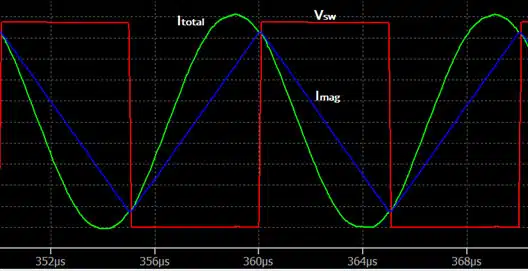
The rate of voltage rise dv/dt of the switching transition depends on the total capacitance to be charged/discharged (2*Coss_tr) and the actual peak current level, as shown in the figure 3. above. The usual 50-100ns of rise/fall times in 400V systems yields good results overall.

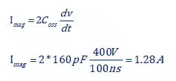
The magnetizing current swings triangularly from a maximum positive to a maximum negative value in T/2 as seen in Figure 3. At the moment of switching to get the 1.28A we just calculated, the current need to swing from -1.28A to +1.28A thus a ΔΙ=2Imag is the current swing.

Using the basic formula for an inductor:

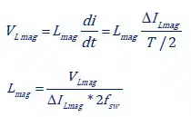
The voltage at the magnetizing Inductor is approximately half of the switching voltage because of the DC bias removal action of the resonant capacitor. So, in the end:

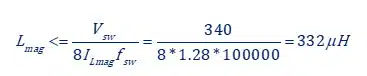
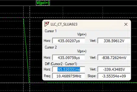
o achieve 100ns of switching time (0-100% of the voltage) we should select the magnetizing inductance below 332μH. Checking out LTspice in Figure 4 we can verify the correctness of the previous steps.

Figure 4. Switching time at ~95ns close to the 100ns target

Conclusion

Proper selection of the magnetizing inductance ensures ZVS conditions over an extensive input voltage range. Of course, lowering the magnetizing inductance comes with the price tag. Reduced efficiency number at light loads (especially) is observed because of the increase in resonant current.

Related

Source: Frenetic

Recent Posts

Coilcraft Releases 0402 Ferrite-Core Wirewound Chip Inductors for RF and EMI Control

25.6.2026
8

Using a Virtual Anode Thermal Model to Evaluate Miniaturization Risk in Tantalum Capacitors

24.6.2026
17

Bourns Introduced High-Current Coupled Inductor for 48 V Hybrid and IBC Converters

24.6.2026
16

Würth Elektronik Expands Nanocrystalline Cable Cores for Broadband EMI Suppression

23.6.2026
16

EMC‑Compliant PCB and Connector Design Guidelines

22.6.2026
34

Practical Value of Structural Diagnostics for Tantalum Capacitor Anodes

22.6.2026
24

Bourns Releases Automotive Gate Driver Transformer for Isolated Power

22.6.2026
20

Vishay Unveils 1.5 kV IHDV High Voltage Power Inductors for EV and Industrial Converters

19.6.2026
35

Würth Elektroniks Flexible EMI Shielding Sheets Provides Quick and Easy Schielding Solution

17.6.2026
48

Upcoming Events

Jun 30
17:00 - 18:00 CEST

PSMA Capacitor Committee Webinar: High Voltage Pulse Capacitors

Jul 14
16:00 - 17:00 CEST

EMC Design Essentials: Mastering Varistors and Common Mode Chokes

Jul 21
16:00 - 17:00 CEST

Safety by design: X and Y Interference suppression capacitors for power line filters

View Calendar

Popular Posts

  • Boost Converter Design and Calculation

    0 shares
    Share 0 Tweet 0
  • Buck Converter Design and Calculation

    0 shares
    Share 0 Tweet 0
  • LLC Resonant Converter Design and Calculation

    0 shares
    Share 0 Tweet 0
  • Flyback Converter Design and Calculation

    0 shares
    Share 0 Tweet 0
  • MLCC and Ceramic Capacitors

    0 shares
    Share 0 Tweet 0
  • Earthing Systems and IEC Classification Explained

    0 shares
    Share 0 Tweet 0
  • Nvidia Vera Rubin: Why One AI Rack Needs So Many More MLCC Capacitors

    0 shares
    Share 0 Tweet 0
  • Dual Active Bridge (DAB) Topology

    0 shares
    Share 0 Tweet 0
  • SEPIC Converter Design and Calculation

    0 shares
    Share 0 Tweet 0
  • MLCC Case Sizes Standards Explained

    0 shares
    Share 0 Tweet 0

Newsletter Subscription


Passive Components Blog

© EPCI - Leading Passive Components Educational and Information Site

  • Home
  • Privacy Policy
  • EPCI Membership & Advertisement
  • About

No Result
View All Result
  • Home
  • Knowledge Blog
  • Dossiers
  • PCNS

© EPCI - Leading Passive Components Educational and Information Site

This website uses cookies. By continuing to use this website you are giving consent to cookies being used. Visit our Privacy and Cookie Policy.
Go to mobile version