


Did you know how to design a simple and elegant solution to power a 5-volt rail using just a single supercapacitor ? This article written by Steven Keeping, published by DigiKey, explains how to use a single 2.7V supercapacitor on 5V rail combined with a reversible buck/boost voltage converter.
Once limited to mission-critical devices, backup power solutions are now in demand for a wide range of electronics applications in industrial, commercial, and consumer end-products. While there are several options, the supercapacitor offers the most compact and energy-dense solution as an energy reservoir when the main supply is interrupted. For example, when there’s a mains power outage or when batteries are being swapped out.
However, supercapacitors introduce design challenges because each device can only provide up to 2.7 volts. That potentially means multiple supercapacitors are needed—each with associated cell balancing and step-up (boost) or step-down (buck) voltage converters—to supply regulated power to a 5-volt power rail. The result is a complex and nuanced circuit that is relatively expensive and takes up excessive board space.
But have a look at another option described in this article.
Design considerations for supercapacitors
If an electronic product is to rely on a supercapacitor for backup power, it is vital that the designer understands how to select the best component for reliable energy storage and delivery, and long life.
One of the first things to check on the datasheet is the effect of temperature on capacitance and resistance. It is good design practice to select a device that exhibits very little change across the intended operating temperature range of the end-product such that if backup power is needed, the supplied voltage is stable, and energy is delivered efficiently.
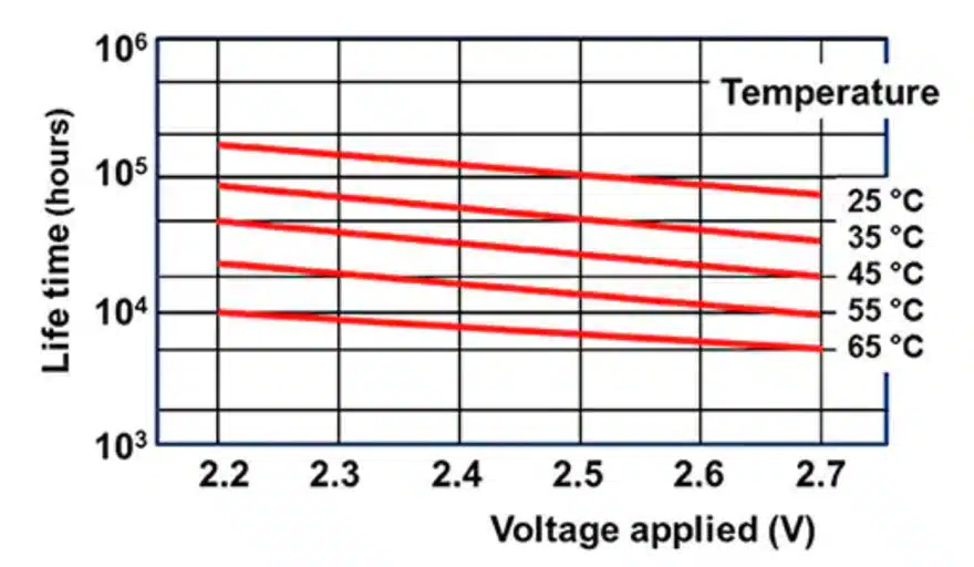
Supercapacitor lifetime is largely determined by the combined effect of operating voltage and temperature (Figure 1). The supercapacitor rarely fails catastrophically. Instead, its capacitance and internal resistance change over time and gradually degrade performance until the component is no longer able to meet the end-product specification. The performance decline is typically greater at the beginning of the end-product’s life, tailing off as the end-product ages.
When used in a backup power application, the supercapacitor will be maintained at the working voltage for long periods, only very occasionally being called upon to discharge its stored energy. This will eventually impact performance. The datasheet will indicate the decline in capacitance over time for typical operating voltages and at different temperatures. For example, a 15% reduction in capacitance and a 40% increase in internal resistance may occur for a supercapacitor held at 2.5 volts for 88,000 hours (10 years) at 25˚C. Such performance decline should be considered when designing backup devices for end-products with long service lives.
The time constant for a capacitor is the time taken for the device to reach 63.2% of full charge or discharge to 36.8% of full charge. The time constant of a supercapacitor is around one second; this is much shorter than an electrolytic capacitor. Because of this short time constant, the designer should ensure that the backup power supercapacitor is not exposed to a continuous ripple current, as damage may result.
Supercapacitors can operate between 0 volts and their maximum rated capacity. While efficient utilization of the supercapacitor’s available energy and power storage is achieved when operating over the widest voltage range, most electronic components have a minimum voltage threshold. This minimum voltage requirement limits the amount of energy that can be drawn from the capacitor.
For example, the energy stored in the capacitor is E = ½CV2. From this relationship, it can be calculated that approximately 75% of the available energy is accessible if the system operates at half the rated voltage of the capacitor (for example from 2.7 to 1.35 volts).
Supercapacitor Balancing – Design challenges when using multiple supercapacitors
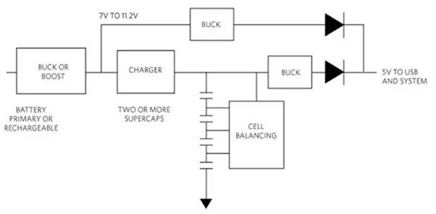
While the advantages of supercapacitors make them suitable for providing backup power to a wide range of electronic products, the designer must be wary of the design challenges they introduce. Implementing a backup power supply circuit can be a significant undertaking for the inexperienced engineer. The key complexity is that commercial supercapacitors are rated for around 2.7 volts, so to supply a typical 5-volt power rail, two supercapacitors must be used in series (Figure 2).
While this is a satisfactory working solution, it incurs additional cost and complexity because of the need for active or passive cell balancing. Due to capacitance tolerances, different leakage currents, and different ESRs, the voltage across two or more nominally identical and fully charged capacitors can be different. This voltage imbalance results in one supercapacitor in a backup circuit supplying a greater voltage than the other. As the temperature increases and/or the supercapacitors age, this voltage imbalance can increase to the point where the voltage across one supercapacitor exceeds that device’s rated threshold and impacts operational life.
Cell balancing in low-duty-cycle applications is typically achieved by placing a bypass resistor in parallel with each cell. The value of the resistor is chosen to be a value that allows any current flow to dominate the total supercapacitor leakage current. This technique effectively ensures that any variation in equivalent parallel resistance between the supercapacitors is negligible. For example, if the supercapacitors in the backup circuit have an average leakage current of 10 microamps (μA), a 1% resistor will allow a current bypass of 100 μA, boosting the average leakage current to 110 μA. In doing so, the resistor effectively decreases the variation in leakage current between the supercapacitors from tens of percent to just a few percent.
With all parallel resistances fairly well matched, any supercapacitors with higher voltages will discharge through their parallel resistance at a higher rate than the supercapacitors with lower voltages. This distributes the total voltage evenly across the entire series of supercapacitors. For high-duty applications, more sophisticated supercapacitor balancing is required.
Using a single supercapacitor for a 5-volt supply
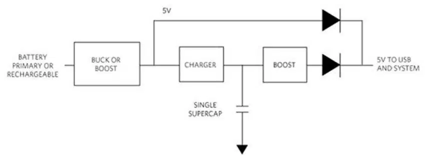
The backup power supply circuit could be made less complex and take up less space if a single supercapacitor is employed instead of two or more. Such an arrangement eliminates the need for supercapacitor balancing. However, the 2.7-volt output from a single device needs to be increased using a boost voltage regulator, creating a sufficient voltage to overcome the voltage drop across a diode and provide 5 volts to the system. The supercapacitor is charged by a charging device and discharges through the boost converter when needed. Diodes allow either the primary power source or the supercapacitor to power the system (Figure 3).
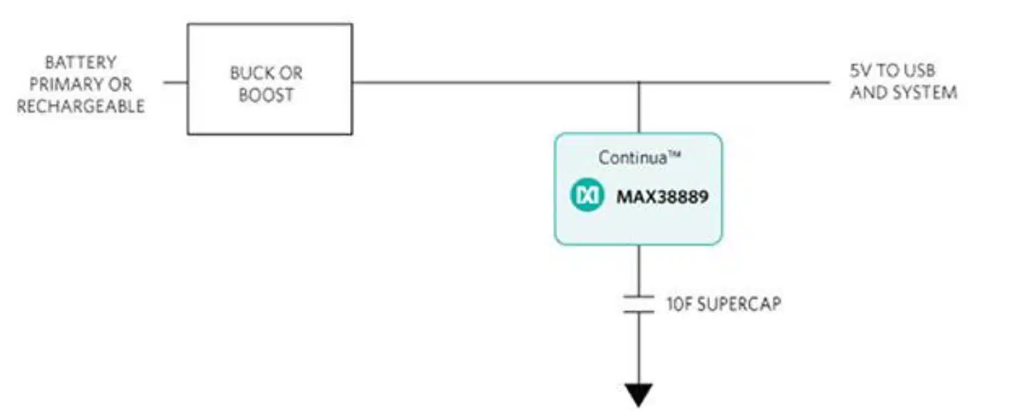
A more elegant solution is to use a single capacitor complemented by a specialized voltage converter, such as Maxim Integrated’s MAX38888 or MAX38889 reversible buck-boost voltage regulator. The former offers 2.5 volts to 5 volts and up to 2.5 amperes (A) output, while the latter is a 2.5-volt to 5.5-volt, 3 A output device (Figure 4).
The MAX38889 is a flexible storage capacitor or capacitor bank backup regulator for transferring power efficiently between the supercapacitor(s) and a system supply rail. When the main supply is present and its voltage is above the minimum threshold system supply voltage, the regulator operates in charging mode and charges the supercapacitor with a maximum 3 A peak, 1.5 A average inductor current. The supercapacitor needs to be fully charged to enable backup operation. Once the supercapacitor is charged, the circuit draws only 4 μA of current while maintaining the component in its ready state.
When the main supply is removed, the regulator prevents the system from dropping below the set system backup operating voltage by boosting the supercapacitor voltage to the required system voltage at a programmed peak inductor current, up to a maximum of 3 A. The reversible regulator can operate down to a supercapacitor supply voltage of just 0.5 volts, maximizing the stored energy use.
The duration of backup depends on the supercapacitor’s energy reserve and the system power draw. The features of the Maxim Integrated products allow for maximum backup power from a single 2.7-volt supercapacitor, while reducing the number of circuit components by eliminating the need for separate charger and boost devices, and diodes.
Conclusion
Supercapacitors offer several advantages over secondary batteries for backup power in particular applications, such as those that demand frequent battery changes. Compared with rechargeable batteries, supercapacitors charge more quickly, can be cycled many more times, and offer much higher power density. However, their maximum 2.7-volt output introduces some design challenges when looking to back up a typical 5-volt supply.
As shown, reversible step-down/step-up voltage regulators offer an elegant solution by allowing a single supercapacitor to back up a 5-volt line while minimizing space and the number of required components.


