Passive Components Blog
No Result
View All Result
  • Home
  • NewsFilter
    • All
    • Aerospace & Defence
    • Antenna
    • Applications
    • Automotive
    • Capacitors
    • Circuit Protection Devices
    • electro-mechanical news
    • Filters
    • Fuses
    • Inductors
    • Industrial
    • Integrated Passives
    • inter-connect news
    • Market & Supply Chain
    • Market Insights
    • Medical
    • Modelling and Simulation
    • New Materials & Supply
    • New Technologies
    • Non-linear Passives
    • Oscillators
    • Passive Sensors News
    • Resistors
    • RF & Microwave
    • Telecommunication
    • Weekly Digest

    Researchers Demonstrated High Energy Ceramic Capacitors Stable in Wide Temperature Range

    Stackpole Offers High Voltage Plate Resistors up to 40KV

    How to Manage Supercapacitors Leakage Current and Self Discharge 

    Qualification of Commercial Supercapacitors for Space Applications

    Experimental Evaluation of Wear Failures in SMD Inductors

    Resonant Capacitors in High-Power Resonant Circuits

    a Schematic diagram of the BNT-based components constructed based on the entropy-increase strategy. b Digital photograph, cross-sectional SEM image, and EDS mappings of the MLCCs. c Unipolar P-E loops of MLCCs as a function of applied E. d Wrec and η of the MLCCs as a function of applied E. The comparison of (e) Wrec and η, (f) η and UF of the MLCCs with those of other recently reported state-of-the-art MLCCs. source: Nature Communications

    Researchers Proposed Enhanced Energy Storage MLCC

    Littelfuse Releases First Reflow-Compatible Illuminated Tactile Switch

    Vishay Unveils 5W Power Metal Strip Resistor in Compact 1206 Case Size

    Trending Tags

    • Ripple Current
    • RF
    • Leakage Current
    • Tantalum vs Ceramic
    • Snubber
    • Low ESR
    • Feedthrough
    • Derating
    • Dielectric Constant
    • New Products
    • Market Reports
  • VideoFilter
    • All
    • Antenna videos
    • Capacitor videos
    • Circuit Protection Video
    • Filter videos
    • Fuse videos
    • Inductor videos
    • Inter-Connect Video
    • Non-linear passives videos
    • Oscillator videos
    • Passive sensors videos
    • Resistor videos

    Efficient Power Converters: Duty Cycle vs Conduction Losses

    Ripple Steering in Coupled Inductors: SEPIC Case

    SEPIC Converter with Coupled and Uncoupled Inductors

    Coupled Inductors in SEPIC versus Flyback Converters

    Non-Linear MLCC Class II Capacitor Measurements Challenges

    Percolation Phenomenon and Reliability of Molded Power Inductors in DC/DC converters

    Root Causes and Effects of DC Bias and AC in Ceramic Capacitors

    How to Calculate the Output Capacitor for a Switching Power Supply

    Switched Capacitor Converter Explained

    Trending Tags

    • Capacitors explained
    • Inductors explained
    • Resistors explained
    • Filters explained
    • Application Video Guidelines
    • EMC
    • New Products
    • Ripple Current
    • Simulation
    • Tantalum vs Ceramic
  • Knowledge Blog
  • Suppliers
    • Who is Who
  • Events
No Result
View All Result
Passive Components Blog
No Result
View All Result

Hybrid dc-dc converter stirs switched capacitor into buck step-down

24.8.2022
Reading Time: 2 mins read
A A

source: Electronics Weekly article

Analogue Devices has combined switched capacitor and inductive buck conversion in the same topology to reduce the size of step-down dc-dc converters.

RelatedPosts

Researchers Demonstrated High Energy Ceramic Capacitors Stable in Wide Temperature Range

Stackpole Offers High Voltage Plate Resistors up to 40KV

How to Manage Supercapacitors Leakage Current and Self Discharge 

Called LTC7821, this is “industry first hybrid step-down synchronous controller that merges a switched capacitor circuit with a synchronous step-down controller, enabling up to a 50% reduction in DC/DC converter solution size compared to traditional step-down solutions,” claims Analog. “This improvement is enabled by a thee times higher switching frequency without compromising efficiency. Alternatively, when operating at the same frequency, a LTC7821-based solution can provide up to 3% higher efficiency.”

The design appears to own a lot to the 500W LTC7820 fixed ratio dc-dc converter the firm launched in July last year.

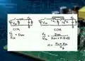
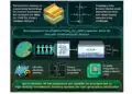
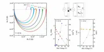
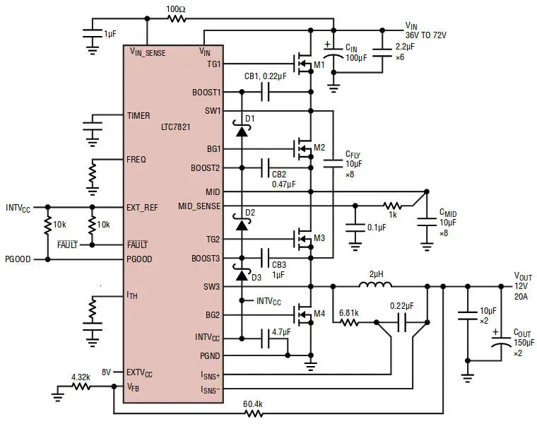
In the LTC7821 hybrid design, the mosfets switch in pairs (see featured image diagram) with M1 and M3 together, alternating with M2 and M4 together.

The first thing this does, through switching interaction between Cfly and Cmid, is to maintain Vin/2 on the top of Cmid – affectively the input to the buck converter.

However, switching timing is controlled by a current-mode loop monitoring the inductor:

  • M1 and M3 are turned on by a latch set by the main clock, then turned off when the inductor current hits a threshold resetting the latch. M2 and M4 are then turned on.
  • Peak inductor current is controlled by the output voltage error amplifier – relative to a 0.8V on-chip (or an optional external reference).
  • M2 and M4 are kept on until the inductor current starts to reverse or the beginning of the next clock cycle.
  • M3 and M4 operate in a manner similar to traditional buck converter, with M3 hard switching and M4 soft-switching at zero voltage.

Just as with the earlier LTC7820, the LTC1821 has a start-up mode in which Cfly and Cmid are pre-charged to Vin/2 before main switching is initiated to prevent huge currents flowing. The two chips also share a totem-pole scheme (see Schottky diode chain) which supplies boot-strap voltages to the internal n-channel mosfet drivers.

The chip operates over 10-72V (80V absolute max) producing outputs from 0.9 to 33.5V with current measured in 10s of amps – depending on the external components.

LTC7821-12Vout-efficiency
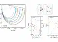
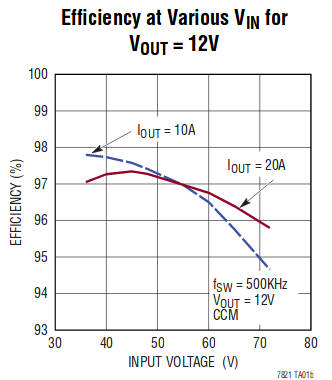
In a typical 48V to 12V 20A application, said the firm, 97% efficiency is attainable at 500kHz: “The same efficiency can only be achieved in a traditional synchronous step-down converter by switching at one-third the operating frequency, resulting in the use of much larger magnetics and output filter components.”

Switching is fixed-frequency, programmable from 200kHz to 1.5MHz.

Mosfet drivers have 1Ω outputs – low enough to drive multiple mosfets in parallel, said Analogue, and the current mode control also allows multiple LTC7821s to current-share in multi-phase parallel configurations.

Other claims for the hybrid arrangement are low EMI and reduced MOSFET stress due to the soft-switched front end.

Non-isolated intermediate bus applications are expected in power distribution, datacoms, telecoms and 48V automotive systems.

Related

Recent Posts

Researchers Demonstrated High Energy Ceramic Capacitors Stable in Wide Temperature Range

2.10.2025
1

Stackpole Offers High Voltage Plate Resistors up to 40KV

2.10.2025
1

How to Manage Supercapacitors Leakage Current and Self Discharge 

1.10.2025
12

Qualification of Commercial Supercapacitors for Space Applications

1.10.2025
8

Experimental Evaluation of Wear Failures in SMD Inductors

1.10.2025
14

Resonant Capacitors in High-Power Resonant Circuits

1.10.2025
8
a Schematic diagram of the BNT-based components constructed based on the entropy-increase strategy. b Digital photograph, cross-sectional SEM image, and EDS mappings of the MLCCs. c Unipolar P-E loops of MLCCs as a function of applied E. d Wrec and η of the MLCCs as a function of applied E. The comparison of (e) Wrec and η, (f) η and UF of the MLCCs with those of other recently reported state-of-the-art MLCCs. source: Nature Communications

Researchers Proposed Enhanced Energy Storage MLCC

1.10.2025
9

Littelfuse Releases First Reflow-Compatible Illuminated Tactile Switch

1.10.2025
2

Vishay Unveils 5W Power Metal Strip Resistor in Compact 1206 Case Size

1.10.2025
10

Improving SMPS Performance with Thermal Interface Material

30.9.2025
6

Upcoming Events

Oct 8
11:00 - 12:00 CEST

PCB Online Shop – simply “Made in Germany” by Würth Elektronik

Oct 14
16:00 - 17:00 CEST

Smart Sensors, Smarter AI: Building Reliable Edge Systems

Oct 17
12:00 - 14:00 EDT

External Visual Inspection per MIL-STD-883 TM 2009

Oct 20
October 20 - October 23

Digital WE Days 2025 – Virtual Conference

Oct 21
October 21 @ 12:00 - October 23 @ 14:15 EDT

Space and Military Standards for Hybrids and RF Microwave Modules

View Calendar

Popular Posts

  • Buck Converter Design and Calculation

    0 shares
    Share 0 Tweet 0
  • Boost Converter Design and Calculation

    0 shares
    Share 0 Tweet 0
  • Flyback Converter Design and Calculation

    0 shares
    Share 0 Tweet 0
  • LLC Resonant Converter Design and Calculation

    0 shares
    Share 0 Tweet 0
  • SEPIC Converter Design and Calculation

    0 shares
    Share 0 Tweet 0
  • Dual Active Bridge (DAB) Topology Explained

    0 shares
    Share 0 Tweet 0
  • Ripple Current and its Effects on the Performance of Capacitors

    3 shares
    Share 3 Tweet 0
  • What is a Dielectric Constant and DF of Plastic Materials?

    4 shares
    Share 4 Tweet 0
  • Flying Capacitors Explained

    0 shares
    Share 0 Tweet 0
  • MLCC and Ceramic Capacitors

    0 shares
    Share 0 Tweet 0

Newsletter Subscription


Passive Components Blog

© EPCI - Leading Passive Components Educational and Information Site

  • Home
  • Privacy Policy
  • EPCI Membership & Advertisement
  • About

No Result
View All Result
  • Home
  • Knowledge Blog
  • Premium Suppliers

© EPCI - Leading Passive Components Educational and Information Site

This website uses cookies. By continuing to use this website you are giving consent to cookies being used. Visit our Privacy and Cookie Policy.
Go to mobile version