In this article, we explore pros and cons of typical design choices for powering remote IoT devices. In the end, we identify ways to maximize performance and operating life, while maintaining the discrete design that IoT devices should have in smart city, industry 4.0, and agricultural applications.
IoT devices are becoming increasingly popular and are being applied in uniquely creative ways every day. With their appeal of open-source software, secure wireless data transfer, and endless capabilities of applications, their appeal is obvious. As technology progresses, low-power data harvesting applications are being explored further every day. However, a common issue encountered with IoT devices is the short operating life of the battery powering them.
When using a battery-powered IoT device, it’s important to minimize the amount of required maintenance and maximize its operating life to avoid costly replacements. Batteries make this a challenge, given their short cycle life. Energy harvesting solutions, such as indoor solar cells, are growing in popularity, as is pairing supercapacitors with these energy harvesting technologies to significantly reduce the burden on the batteries. This is because supercapacitors excel at charging with very small levels of current, have a high cycle life, and can deliver large amounts of current in quick bursts to complement batteries. In certain applications, supercapacitors can even replace the batteries all together.
Example IoT Scenario
Let’s design an IoT device to monitor air temperature throughout a city. In this case, the city management wants IoT devices installed in select intersections throughout the city. The customer’s key requirements are:
- No change / retrofit to any of city infrastructure
- Added sensors and enclosures must be discrete and not an eyesore
- Hourly temperature readings through the day and night
- Data transmission every three hours via cellular network
- Maintenance free, with a targeted 10-year operating life
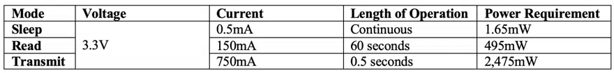
The system requires 3.3V and will feature three modes of operation: sleep, read, and transmit. The system will primarily operate in its sleep mode, where very little energy or power is required. Read mode will run for 60 seconds every hour, during which the sensor will record the temperature and store that data in memory. Finally, the system will transmit its data (the air temperature readings) for 0.5 seconds once every three hours to its receiver.
Design Choices
Battery:
Using only a battery to power this design is the easiest way to go in terms of design simplicity, but it will not meet the customer’s requirements. Either the battery must be so large so that it stores enough energy to power the system for 10 years without maintenance or it will regularly require replacements of smaller batteries. The peak power requirement may require a smaller battery to discharge at a higher C rate, which may be harmful to the battery.
PRO: Easy, simple design
CON: Very large batteries needed or costly frequent replacements of smaller batteries
Potential fix: Add solar cell energy harvesting to help support the battery during periods of sunlight
Solar + Battery:
A solar cell in this kind of design will reduce the burden of the battery by delivering power to the load, reducing the burden on the battery and may be able to recharge the battery during the system’s sleep mode. It is a step in the right direction but does not perfectly satisfy the customer’s requirements.
If a large battery is used, it will recharge very slowly with the help of the solar cell. A solar cell could recharge a smaller battery faster, but that smaller battery would cycle faster, reducing the operating life. A battery may have a ~500 cycle life before significantly degrading in performance.
If the battery is sized to provide 24 hours of operation on its own, it will likely need to be replaced every few years. Also, a smaller battery may be damaged during the high discharge rate seen in the transmit mode further shortening its life.
If the battery is sized to provide 720 hours (approximately one month) of operation on its own, it may be too large to meet the discrete requirement set by the customer. It may also struggle to recharge with the small current provided by the solar cells. Even if the battery does meet the aesthetic requirements of the customer, a battery powering this device for one month and recharging by a solar cell will not meet the 10-year operating life requirement.
PRO: Solar cell supports the battery during the day reducing the burden on the battery
CON: Still not likely to meet either the aesthetic requirements or service life requirement
Potential fix: Add supercapacitor to complement the system by recharging at small currents and powering transmit mode
Solar + Supercapacitor:
There are a few challenges batteries face in this kind of design.
First, they struggle to charge with small current values from energy harvesting devices like a solar cell. Second, they have a short cycle life, making it riskier to use a smaller battery that can recharge faster with small current values. Third, they can be damaged by discharging at a high C rate, which means they are not well suited for the transmit mode of operation.
A supercapacitor can solve these problems, but do not come without their own challenges.
A supercapacitor features a high-power density, meaning it is well suited to charge with small currents and to respond to high power draws from the load (like the transmit mode). They also can be cycled hundreds of thousands of times without performance degradation, meeting the operating life requirements.
The problems faced with supercapacitors, is that they cannot provide energy for long periods of time. While recharging quickly with morning light, a supercapacitor and solar cell will not power this system through the night. The only way to do this would be to add many supercapacitors to the design to increase the energy storage capacity, but this would increase cost and size of the system failing the customer’s requirements.
PRO: Long service life, easy low current recharging, high power mode for transmitting data
CON: Cannot power device at night, failing to meet customer requirement
Potential Fix: Add a battery to power the system at night
Solar + Battery + Supercapacitor:
This hybrid design allows each component to do what it does best and what it is designed to do.
Solar cells provide energy though the day to power the device and recharge energy storage systems.
Supercapacitors act as a workhorse and handle peak power requirements for the system.
Batteries provide energy though the night.
With this approach, all the requirements set by the customer can be met. The one challenge will be the aesthetic requirement to be discrete. IoT products often have space constraints, making it difficult to find the space to use batteries and supercapacitors. There may only be space for one or the other without needing to make the design larger.
Capacitech’s supercapacitor, the Cable-Based Capacitor (CBC), is a wire-like and flexible energy storage device. It is designed to help engineers add supercapacitors to their designs without being concerned about negative tradeoffs. Leveraging its form factor, the CBC offers engineers a placement advantage so that they can find space to add supercapacitors to their IoT designs by not being restricted to the printed circuit board where space is a premium.
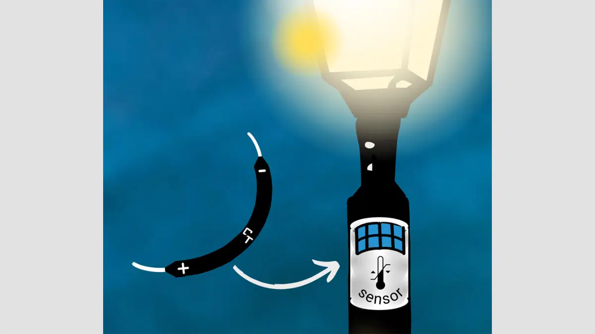
Potential Design
One option to build a solar-battery-supercapacitor hybrid design is to embed the air temperature monitor into a flexible package to be wrapped around a streetlamp where it is out of sight, out of mind using flexible solar cells, flexible CBCs, a narrow pouch style battery, and a skinny circuit board that is vertically aligned with the pole.
From power management devices offered by Texas Instruments, Analog Devices, e-peas, and others, we know that they often require <5V input from solar power and that passive components can be changed to select the charging voltage for the supercapacitor as well as the final output voltage to the load. For this scenario, a power management device will be calibrated to charge the CBCs to 4.5V, discharge them to 3.6V, and regulate the output voltage to be 3.3V.
Selecting Components
We will select PowerFilm’s MP3-37 flexible solar panel. In ideal conditions, the MP3-37 has:
- Harvesting Power: 150mW
- Operating Voltage: 3.0V
- Current: 50mA
- Avg Open Circuit Voltage: 4.1V
- Max Open Circuit Voltage: 4.6V
- Short Circuit Current: 63mA
Two solar cells are connected in parallel to provide <300mW of power to charge the CBCs and power the device in sleep mode. In this design, the solar cells provide power during the day, but since they do not provide enough power to operate the device in read mode or to meet the peak power requirements of 750mA for data transmission, the CBCs are used to complement the solar cells during the day.
One cell of Capacitech’s CBC supercapacitor features:
- Capacitance: 3F
- Rated Voltage: 1.6V
- Rated Max Charge/Discharge Current: 1.25A
At 1.6V, a single CBC cell falls short of the required operating voltage. The energy harvesting power management circuit needs to charge the CBC to 4.5V. To create an arrangement that satisfies this condition, three units of CBCs are connected in series so that the rated voltage of the connected CBCs is greater than 4.5V.
V = (1.6)*(number of cells in series)
V = (1.6)*(3) = 4.8V
And the equivalent capacitance of three CBCs in series is:
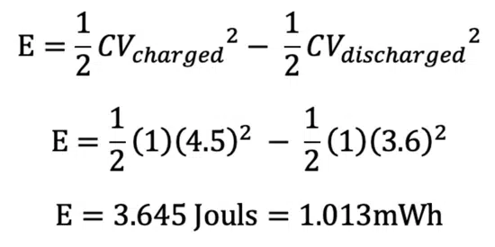
The power management device will charge the CBC to 4.5V and limit its discharge to 3.6V. So the energy stored in the CBCs is:
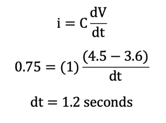
We can also calculate approximately how long a 1F supercapacitor charged to 4.5V can provide the 750mA required for the transmit mode for.
If we consider that the transmit mode draws 2.475W for 0.5 seconds, then it requires approximately 0.353mWh. Thus, three CBCs connected in series featuring a 1F and 4.8V rating, is sufficient to power the data transmission. The CBC supercapacitors here are used to complement the solar cells during the day and protect the battery from damaging high discharge rates. Also, this configuration of CBCs will allow them to charge quickly, even during low light time periods (sunrise, sunset, or under shade).
Conclusion
This scenario illustrated the benefits of integrated energy harvesting with power management circuits and highlighted the effectiveness of the CBC in the system. This conceptual design would be able to:
- Leverage energy harvesting technology
- Meet peak power requirements for data transmission
- Pair batteries and supercapacitors as an energy storage system
- Use CBC flexible supercapacitors that can be wrapped around a pole
- Reduce the burden on the battery when light is available, so that operating life requirements are met
There is an abundance of other scenarios that could benefit from these systems, and the CBC can prove to be invaluable in making them effective and lasting. There are multiple iterations available to optimize various aspects of this design. This is simply an exploration on how an IoT device can be developed. We would love to hear about your battery powered IoT plans and how we can help you achieve your design goals!