Passive Components Blog
No Result
View All Result
  • Home
  • NewsFilter
    • All
    • Aerospace & Defence
    • Antenna
    • Applications
    • Automotive
    • Capacitors
    • Circuit Protection Devices
    • electro-mechanical news
    • Filters
    • Fuses
    • Inductors
    • Industrial
    • Integrated Passives
    • inter-connect news
    • Market & Supply Chain
    • Market Insights
    • Medical
    • Modelling and Simulation
    • New Materials & Supply
    • New Technologies
    • Non-linear Passives
    • Oscillators
    • Passive Sensors News
    • Resistors
    • RF & Microwave
    • Telecommunication
    • Weekly Digest

    Binder Hybrid Connector Simplifies One Cable Automation

    Tapped Inductor Buck Converter Fundamentals

    TAIYO YUDEN Releases Mini Metal Power Inductors

    Molecular Memristor Shows Record 145 kH Emergent Inductance

    Planar vs Conventional Transformer: When it Make Sense

    Researchers Propose Next‑Gen Compact Memory Using Ultra-thin Ferroelectric Capacitors

    Nichicon ADN Automotive Hybrid Aluminum Capacitors Now Available in EMEA

    Wk 19 Electronics Supply Chain Digest

    Electrocaloric Multilayer Capacitors: Towards Quiet, Solid‑State Cooling Around Room Temperature

    Trending Tags

    • Ripple Current
    • RF
    • Leakage Current
    • Tantalum vs Ceramic
    • Snubber
    • Low ESR
    • Feedthrough
    • Derating
    • Dielectric Constant
    • New Products
    • Market Reports
  • VideoFilter
    • All
    • Antenna videos
    • Capacitor videos
    • Circuit Protection Video
    • Filter videos
    • Fuse videos
    • Inductor videos
    • Inter-Connect Video
    • Non-linear passives videos
    • Oscillator videos
    • Passive sensors videos
    • Resistor videos

    Tapped Inductor Buck Converter Fundamentals

    Planar vs Conventional Transformer: When it Make Sense

    Modeling Fringing Field Losses in Inductors & Transformers

    Why Power Inductors Use a Ferrite Core With an Air Gap

    Transformer-Based Power-Line Harvester Magnetic Design

    Thermal Modeling of Magnetics

    Standard vs Planar LLC transformers Comparison for Battery Chargers

    How Modern Tools Model Magnetic Components for Power Electronics

    Advanced Loss Modeling for Planar Magnetics in the Frenetic Planar Tool

    Trending Tags

    • Capacitors explained
    • Inductors explained
    • Resistors explained
    • Filters explained
    • Application Video Guidelines
    • EMC
    • New Products
    • Ripple Current
    • Simulation
    • Tantalum vs Ceramic
  • Knowledge Blog
  • DossiersNew
  • Suppliers
    • Who is Who
  • PCNS
    • PCNS 2025
    • PCNS 2023
    • PCNS 2021
    • PCNS 2019
    • PCNS 2017
  • Events
No Result
View All Result
Passive Components Blog
No Result
View All Result

Miniaturization – Downsizing of Inductors

2.6.2021
Reading Time: 4 mins read
A A
Figure 1: Inductor Using Ferrite and Iron Powder Technology; source: Chillisin

Figure 1: Inductor Using Ferrite and Iron Powder Technology; source: Chillisin

Space on a PCB is in short supply, but the demands placed on the technical properties of inductive components continue to rise. Choosing the right technology can make the difference in successfully mastering the balancing act between space and performance. Rutronik noted some general guidelines in its blog on miniaturization and inductor downsizing.

In the automotive sector, it has long been standard practice to define the available development space for modules before the development using actual components even begins. In industrial applications, there are also increasingly size restrictions in the interest of saving space, weight and cost. At the same time, the modern designs of many applications require higher currents, higher switching frequencies, higher efficiency levels and better temperature management.

RelatedPosts

Binder Hybrid Connector Simplifies One Cable Automation

Tapped Inductor Buck Converter Fundamentals

TAIYO YUDEN Releases Mini Metal Power Inductors

Power inductors

A conventional application for inductors is filtering electrical interference in a conductor. To filter push-pull interference in a current signal, coils with a single winding are used. It is conventional to use a ferrite core to boost the filter effect, although saturation effects can occur with high currents and temperatures. Coils with much higher buffer inductance values than are actually required for the application are often used as a workaround for this effect. The drawback with this over-specification is that components tend to become significantly larger and more expensive as a result.

An elegant approach to avoiding this is the use of coils with a different core material such as iron or metal powder. Figure 2 shows the inductance curve of ferrite and metal powder chokes as current rising and at different temperatures. The metal powder components exhibit a more stable inductance curve at both 25°C and 150°C compared to the ferrite models.

Figure 2: Typical saturation curve of coils using various technologies with a rated inductance of L0 =22µH and a 10mm x 10mm footprint.

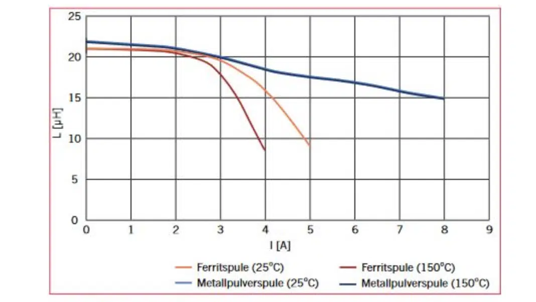
When selecting products for real applications, this enables the use of coils with a lower rated inductance. This generally results in a smaller footprint and consequently also a cheaper component.

Figure 3. Common inductor core materials with their permeability values

The technology and production process of metal power inductors have since adjusted to the needs of the market, satisfying the technical requirements of modern applications and providing a competitive commercial offering.

But it’s still worth taking a closer look at the specifications of the application. Instead of comparing the rated inductance values in the data sheets when selecting components, a more pertinent question would be “which inductance is required with a real current at conventional operating temperatures?” The consistent behavior of metal powder coils also provides the confidence of passing EMC testing reliably.

Transducers and EMI filters

Transducers and EMI filters (electromagnetic interference) are created relatively rarely using standard products – the requirements placed upon these products are simply too diverse. Manufacturers have made great technological strides in the development of these products in recent years. Especially when it comes to power supply units in the field of power electronics, the specifications are often pushed to their limits with conventional ferrite core designs for high-frequency transducers. The transducer is often the tallest component on the PCB, making its miniaturization a matter of some importance. With its large volume, it also plays a significant role in the heating of the system as a whole.

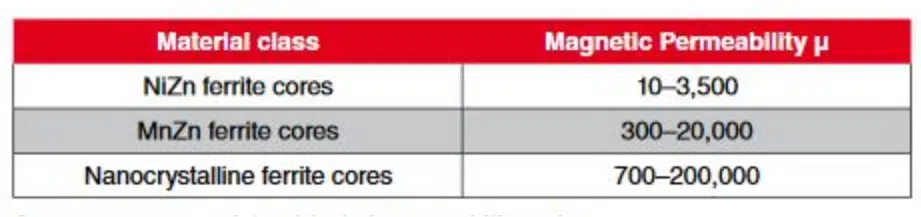
To enable the creation of smaller form factors and more efficient circuits, “nanocrystalline” cores have been developed. These materials offer much greater magnetic permeability (see table), allowing for the generation of higher magnetic flux densities in the component. They also make transducers with a higher switching frequency possible, which means lower losses.

Another trend is open designs that are not encapsulated by a package, but are simply mounted on a base plate to comply with insulation resistance requirements. This saves space and helps better dissipate heat.

Conclusion

There are inductors available today that use different – sometimes novel – materials and designs to meet all of the key requirements of modern applications, namely small size, low weight, higher currents and switching frequencies, and optimized heat control. When selecting components, it is essential to take into account not only the rated values of the inductors, but also the values arising in real applications.

Related

Source: Rutronik

Recent Posts

Tapped Inductor Buck Converter Fundamentals

13.5.2026
10

TAIYO YUDEN Releases Mini Metal Power Inductors

13.5.2026
9

Molecular Memristor Shows Record 145 kH Emergent Inductance

12.5.2026
11

Planar vs Conventional Transformer: When it Make Sense

11.5.2026
35

High-Crystallinity Nanocrystalline Composites for MHz Chip Inductors

7.5.2026
63

Würth Elektronik Introduces Compact Flat-wire SMT Power Inductors for Automotive

5.5.2026
49

Energy Localization in Tantalum Anode Formation: A Structural Perspective

4.5.2026
46

Modeling Fringing Field Losses in Inductors & Transformers

30.4.2026
53

Miniaturization of Tantalum Capacitors: Structural Limit Under Constant Rating

27.4.2026
54

Upcoming Events

May 19
16:00 - 17:00 CEST

Designing Qi2 Wireless Power Systems: Practical Development and EMC Optimization

Jun 2
16:00 - 17:00 CEST

Calculation, Simulation and Measurement of 800V EMC Filters

Jun 16
16:00 - 17:00 CEST

EMC with EMC – EMC‑compliant design with electromechanical connectors

View Calendar

Popular Posts

  • Buck Converter Design and Calculation

    0 shares
    Share 0 Tweet 0
  • Boost Converter Design and Calculation

    0 shares
    Share 0 Tweet 0
  • Flyback Converter Design and Calculation

    0 shares
    Share 0 Tweet 0
  • LLC Resonant Converter Design and Calculation

    0 shares
    Share 0 Tweet 0
  • MLCC and Ceramic Capacitors

    0 shares
    Share 0 Tweet 0
  • Dual Active Bridge (DAB) Topology

    0 shares
    Share 0 Tweet 0
  • What Electronics Engineer Needs to Know About Passive Low Pass Filters

    0 shares
    Share 0 Tweet 0
  • Capacitor Charging and Discharging

    0 shares
    Share 0 Tweet 0
  • Ripple Current and its Effects on the Performance of Capacitors

    3 shares
    Share 3 Tweet 0
  • MLCC Case Sizes Standards Explained

    0 shares
    Share 0 Tweet 0

Newsletter Subscription


Passive Components Blog

© EPCI - Leading Passive Components Educational and Information Site

  • Home
  • Privacy Policy
  • EPCI Membership & Advertisement
  • About

No Result
View All Result
  • Home
  • Knowledge Blog
  • PCNS

© EPCI - Leading Passive Components Educational and Information Site

This website uses cookies. By continuing to use this website you are giving consent to cookies being used. Visit our Privacy and Cookie Policy.
Go to mobile version