Passive Components Blog
No Result
View All Result
  • Home
  • NewsFilter
    • All
    • Aerospace & Defence
    • Antenna
    • Applications
    • Automotive
    • Capacitors
    • Circuit Protection Devices
    • electro-mechanical news
    • Filters
    • Fuses
    • Inductors
    • Industrial
    • Integrated Passives
    • inter-connect news
    • Market & Supply Chain
    • Market Insights
    • Medical
    • Modelling and Simulation
    • New Materials & Supply
    • New Technologies
    • Non-linear Passives
    • Oscillators
    • Passive Sensors News
    • Resistors
    • RF & Microwave
    • Telecommunication
    • Weekly Digest

    Samtec Expands Connector Severe Environment Testing Offering

    Silicon Capacitors Market: Shaping the Foundation for Next-Gen Miniaturization Electronics

    YAGEO Releases Compact Coupled Inductors for High-Density VR Designs

    Enhancing Energy Density in Nanocomposite Dielectric Capacitors

    Advances in the Environmental Performance of Polymer Capacitors

    Vishay Releases DLA Tantalum Polymer Capacitors for Military and Aerospace

    Vishay Expanded Inductor Portfolio With More Than 2000 Stock Items 

    Paumanok Releases Capacitor Foils Market Report 2025-2030

    Modelithics Welcomes CapV as a Sponsoring MVP

    Trending Tags

    • Ripple Current
    • RF
    • Leakage Current
    • Tantalum vs Ceramic
    • Snubber
    • Low ESR
    • Feedthrough
    • Derating
    • Dielectric Constant
    • New Products
    • Market Reports
  • VideoFilter
    • All
    • Antenna videos
    • Capacitor videos
    • Circuit Protection Video
    • Filter videos
    • Fuse videos
    • Inductor videos
    • Inter-Connect Video
    • Non-linear passives videos
    • Oscillator videos
    • Passive sensors videos
    • Resistor videos

    Connector PCB Design Challenges

    Efficient Power Converters: Duty Cycle vs Conduction Losses

    Ripple Steering in Coupled Inductors: SEPIC Case

    SEPIC Converter with Coupled and Uncoupled Inductors

    Coupled Inductors in SEPIC versus Flyback Converters

    Non-Linear MLCC Class II Capacitor Measurements Challenges

    Percolation Phenomenon and Reliability of Molded Power Inductors in DC/DC converters

    Root Causes and Effects of DC Bias and AC in Ceramic Capacitors

    How to Calculate the Output Capacitor for a Switching Power Supply

    Trending Tags

    • Capacitors explained
    • Inductors explained
    • Resistors explained
    • Filters explained
    • Application Video Guidelines
    • EMC
    • New Products
    • Ripple Current
    • Simulation
    • Tantalum vs Ceramic
  • Knowledge Blog
  • Suppliers
    • Who is Who
  • Events
No Result
View All Result
Passive Components Blog
No Result
View All Result

MLCC Selection Guide – Don’t Blindly Leave Component Choices to Tools

10.6.2021
Reading Time: 7 mins read
A A

Miniaturization has long been “en vogue” when it comes to multi-layer ceramic chip capacitors. But downsizing is no trivial process, especially given that there are many marginal conditions to be considered. Digital tools can help, but relying on these can often cause you to lose perspective of key technical issues. Read more in article published by Rutronik.

Multi-layer ceramic chip capacitors (MLCCs) are small and thus useful for miniaturization. But it is also important to consider aspects such as ESD protection, EM interference and heat management, as well as the typical characteristics and the drift that goes hand in hand with these. Digital tools are increasingly being used to make the process of selecting components easier. Even so, developers still need to keep all of the aforementioned aspects in view to be able to achieve their objective quickly and avoid unnecessary re-design work.

RelatedPosts

Samtec Expands Connector Severe Environment Testing Offering

Silicon Capacitors Market: Shaping the Foundation for Next-Gen Miniaturization Electronics

YAGEO Releases Compact Coupled Inductors for High-Density VR Designs

First of all, it is recommended to not simply fall back to existing value combinations of MLCCs when downsizing-especially in terms of capacitance (C value) and voltage-but instead to base decisions on the actual needs of the application and even on the function of the individual components. Ideally, the preferred versions of the suppliers should be considered. Alongside the C value and voltage, other important values include impedance and ESR (equivalent series resistance).

Especially with “hi-caps”, which are MLCCs with C values measured in µFs, the DC bias is also a factor to be taken into consideration. DC bias is an effect that reduces capacitance depending on the applied DC voltage. It can drop to as low as around 20% of the nominal value at the rated voltage, depending on the component, so it is essential to be aware of your absolute minimum C value during operation.

Figure 1 shows a number of examples of DC bias curves. They show that the DC bias rate is much higher with smaller components.

Figure 1: Smaller constructions have a higher DC bias rate.

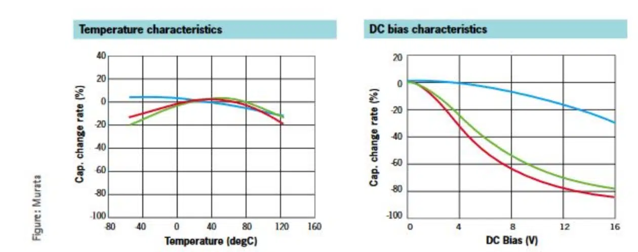
Another factor of influence on DC bias is operating temperature, as illustrated by the graph in Figure 2, which shows that for smaller constructions with higher nominal values, the remaining capacitance over DC bias and temperature is far above that of larger constructions with lower nominal values.

Figure 2: Smaller constructions have a higher residual capacitance than larger ones.

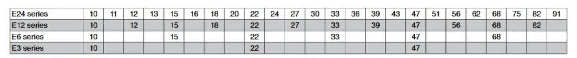
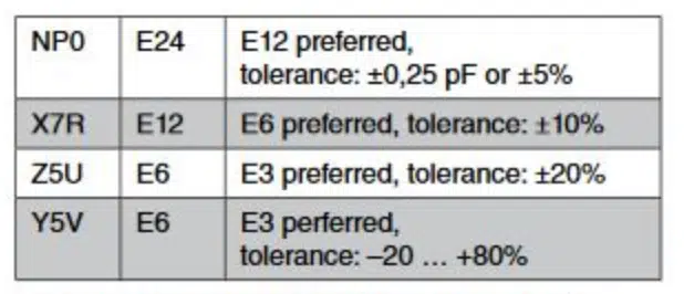
When grading nominal C values, developers should base their choices on the base guide values (Tables 1 to 3), which means that they should ideally only use the “preferred” values with the standard tolerances. In fact, the Z5U and Y5V ceramic types should be left well alone, as they are increasingly being discontinued, and some actually already are discontinued.

Table 1: Capacitance grading
Table 2: Tolerance codes
Table 3: Preferred combinations when selecting MLCCs (capacitance >1µF: E3 series preferred)

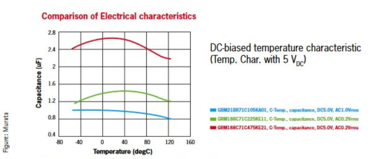
In addition to the issue of DC bias, Class 2 ceramic capacitors (such as X7R, X5R) also have temperature drift and aging to consider.

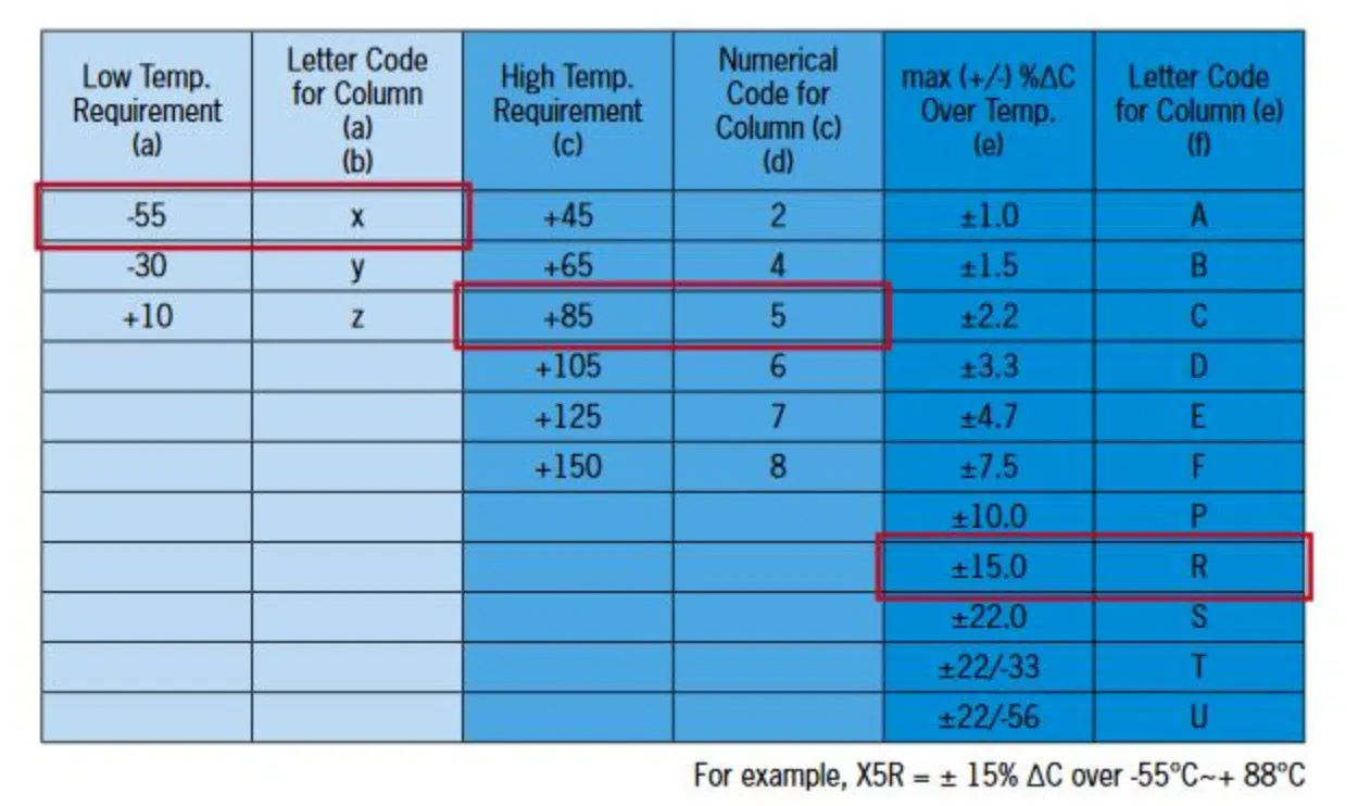
Temperature drift can be relatively easily determined using the table (Table 4 and Figure 3). It shows, for example, that an X5R MLCC has a predictable temperature drift of ±15% in a temperature range of -55°C to +85°C.
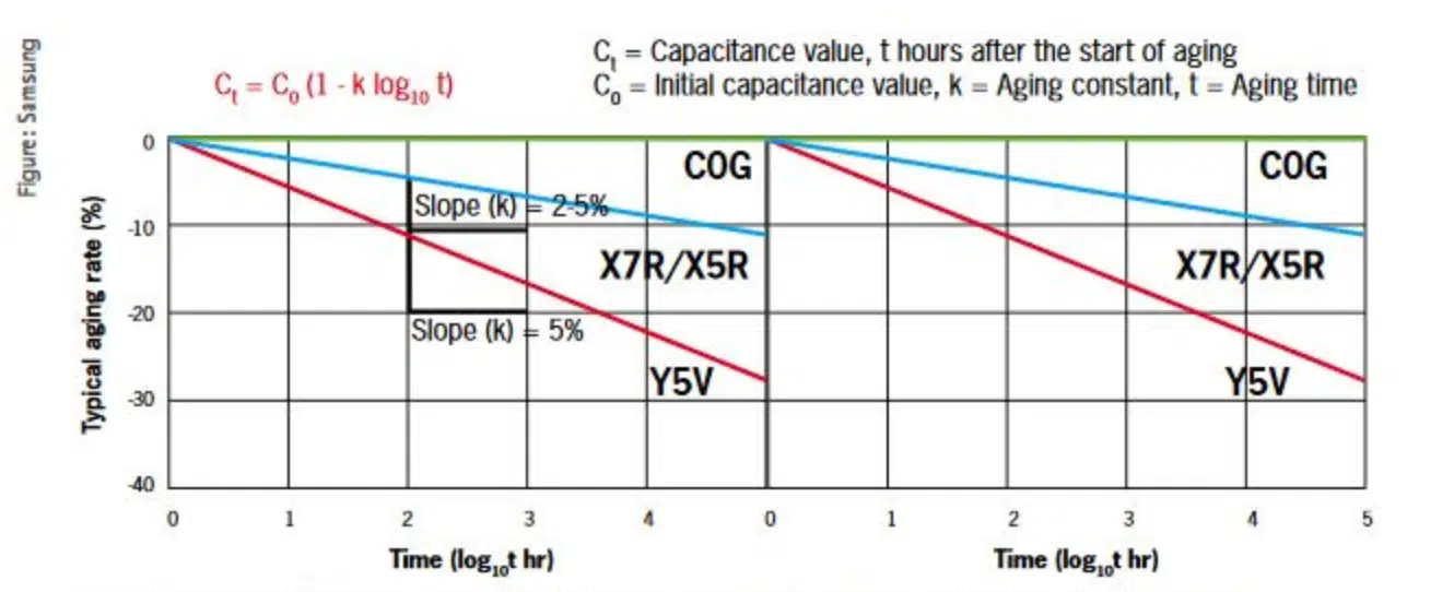
Table 4: Temperature drifts of various MLCCs (source Samsung)

MLCCs also age

Aging causes MLCCs to lose capacitance over time. The loss is between around 1% and 6% per logarithmic decade, which means after 1 hour, after 10 hours, after 100 hours, and so on. As a result, the higher the C values and the thinner the internal layers of an MLCC, the more susceptible the MLCC will be to aging. That said, compared to the effects of DC bias and temperature drift, aging is basically a negligible factor, although it can play a key role when measuring C values for testing tolerances.

Unlike with living beings, MLCC aging is a reversible process. Appropriate heat treatment allows the effect to be reversed. The components are usually exposed to +150°C for an hour, then allowed to rest for 24 hours. Soldering also enables “de-aging”. See Figure 3.

Figure 3: Exposing MLCCs to very high temperatures for a while allows aging effects to be reversed.

Looking at the various C value drifts overall, it becomes apparent that it is not advisable to use Class 2 capacitors with a limited nominal tolerance range of ±5% instead of the standard tolerance range of ±10%-even if some suppliers still offer and deliver this. The result is pointless debates on adherence to tolerance ranges. During measurements, compliance with requirements regarding measuring devices and measurement conditions is frequently inadequate. For example, the measurement voltage, usually with a defined effective value of 1.0V, drops during the measurement, causing the displayed capacitance value to be too low.

Better to Leave some breathing space with voltage requirements

The specified voltage is usually a DC voltage-even if it is not explicitly labeled as such. If the value is an AC voltage, this will be declared accordingly (e.g. “250V AC”). Additional details and information, for example relating to ripple current, peak-to-peak etc. are usually provided by suppliers in their detailed data sheets or in their specification/application information. It is important to note here though that MLCCs that have the same C value but a higher dielectric strength (regardless of predictability or error rate aspects) tend to have thicker interior layers, which results in a less pronounced DC bias.

That said, some suppliers continue to provide lower voltage specifications for capacitors that today support voltages of 50V, for example.

In either of these two cases, it is ultimately not a problem to exceed voltage requirements, for example by using a capacitor specified for 25V or 50V with a requirement of 16V.

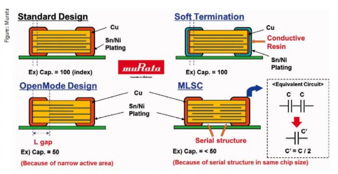
Alongside the base parameters considered here, there are a number of other aspects that play a role when selecting components, for example the required quality level or properties, depending on the application and field of use. Such properties may include Automotive Grade (usually AEC-Q200-qualified) or soft termination (also known as flexiterm, flexcrack resistant, resin external electrode, polymer termination among other similar expressions), which prevents the formation of cracks that notably can occur when bending PCBs (Figure 4).

Figure 4: MLCCs with specific properties can also meet special requirements.

Motivation for miniaturization

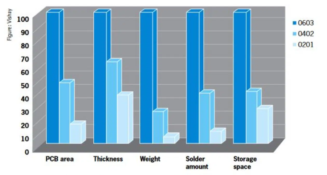
Miniaturization has other implications arising from the motivation behind them. While it may have been driven until recently by the demand for modern electronics to provide more and more performance, which increasingly limited the amount of space on the PCB, the primary factors today are more likely to be availability and cost-effectiveness (Figure 5), especially among suppliers. For developers, this means that they increasingly have to adapt to the pace of the suppliers and leave enough leeway for alternatives if they want to stay flexible and cost-effective-double-sourcing being key to this. This is especially true in the midst of challenging market conditions, which can always arise, even if just temporarily.

Figure 5: Cost-effectiveness comparison of various construction sizes

Further references to MLCC BIAS Ageing issues

High CV MLCC DC BIAS and AGEING Capacitance Loss Explained

Related

Source: Rutronik

Recent Posts

Silicon Capacitors Market: Shaping the Foundation for Next-Gen Miniaturization Electronics

10.10.2025
8

Enhancing Energy Density in Nanocomposite Dielectric Capacitors

9.10.2025
14

Advances in the Environmental Performance of Polymer Capacitors

8.10.2025
31

Vishay Releases DLA Tantalum Polymer Capacitors for Military and Aerospace

8.10.2025
15

Paumanok Releases Capacitor Foils Market Report 2025-2030

7.10.2025
16

Modelithics Welcomes CapV as a Sponsoring MVP

7.10.2025
3

Benefits of Tantalum Powder Stress–Strain Curve Evaluation vs Conventional Wet Test

3.10.2025
23

Electrolyte Selection and Performance in Supercapacitors

3.10.2025
31

Connector PCB Design Challenges

3.10.2025
34

Researchers Demonstrated High Energy Ceramic Capacitors Stable in Wide Temperature Range

2.10.2025
24

Upcoming Events

Oct 14
16:00 - 17:00 CEST

Smart Sensors, Smarter AI: Building Reliable Edge Systems

Oct 17
12:00 - 14:00 EDT

External Visual Inspection per MIL-STD-883 TM 2009

Oct 20
October 20 - October 23

Digital WE Days 2025 – Virtual Conference

Oct 21
October 21 @ 12:00 - October 23 @ 14:15 EDT

Space and Military Standards for Hybrids and RF Microwave Modules

Oct 28
8:00 - 15:00 CET

Power Up Your Design: SN6507 and the Ready-to-Use Development Kit

View Calendar

Popular Posts

  • Buck Converter Design and Calculation

    0 shares
    Share 0 Tweet 0
  • Boost Converter Design and Calculation

    0 shares
    Share 0 Tweet 0
  • Flyback Converter Design and Calculation

    0 shares
    Share 0 Tweet 0
  • LLC Resonant Converter Design and Calculation

    0 shares
    Share 0 Tweet 0
  • What is a Dielectric Constant and DF of Plastic Materials?

    4 shares
    Share 4 Tweet 0
  • SEPIC Converter Design and Calculation

    0 shares
    Share 0 Tweet 0
  • Dual Active Bridge (DAB) Topology Explained

    0 shares
    Share 0 Tweet 0
  • Ripple Current and its Effects on the Performance of Capacitors

    3 shares
    Share 3 Tweet 0
  • MLCC and Ceramic Capacitors

    0 shares
    Share 0 Tweet 0
  • Flying Capacitors Explained

    0 shares
    Share 0 Tweet 0

Newsletter Subscription


Passive Components Blog

© EPCI - Leading Passive Components Educational and Information Site

  • Home
  • Privacy Policy
  • EPCI Membership & Advertisement
  • About

No Result
View All Result
  • Home
  • Knowledge Blog
  • Premium Suppliers

© EPCI - Leading Passive Components Educational and Information Site

This website uses cookies. By continuing to use this website you are giving consent to cookies being used. Visit our Privacy and Cookie Policy.
Go to mobile version