Passive Components Blog
No Result
View All Result
  • Home
  • NewsFilter
    • All
    • Aerospace & Defence
    • Antenna
    • Applications
    • Automotive
    • Capacitors
    • Circuit Protection Devices
    • electro-mechanical news
    • Filters
    • Fuses
    • Inductors
    • Industrial
    • Integrated Passives
    • inter-connect news
    • Market & Supply Chain
    • Market Insights
    • Medical
    • Modelling and Simulation
    • New Materials & Supply
    • New Technologies
    • Non-linear Passives
    • Oscillators
    • Passive Sensors News
    • Resistors
    • RF & Microwave
    • Telecommunication
    • Weekly Digest

    Top 10 Connector Vendors by Product Type

    Bourns Releases High‑Q Air Coil Inductors for RF Aplications

    CMSE 2026 Announces Call for Presentations on High-Reliability Military and Space Electronics

    ESA Call for Papers 6th Space Passive Component Days – SPCD 2026

    Würth Elektronik Offers Halogen‑Free EMC Gaskets for Displays and Housings

    Component Distribution Supply Chain January 2026

    Binder Unveils M8 Flange Solder Connectors for Flexible Cabling

    Power Electronics Tools for Passives and Magnetic Designs

    Modelithics Releases Component Model Library for SIMULIA CST Studio Suite

    Trending Tags

    • Ripple Current
    • RF
    • Leakage Current
    • Tantalum vs Ceramic
    • Snubber
    • Low ESR
    • Feedthrough
    • Derating
    • Dielectric Constant
    • New Products
    • Market Reports
  • VideoFilter
    • All
    • Antenna videos
    • Capacitor videos
    • Circuit Protection Video
    • Filter videos
    • Fuse videos
    • Inductor videos
    • Inter-Connect Video
    • Non-linear passives videos
    • Oscillator videos
    • Passive sensors videos
    • Resistor videos

    One‑Pulse Characterization of Nonlinear Power Inductors

    Thermistor Linearization Challenges

    Coaxial Connectors and How to Connect with PCB

    PCB Manufacturing, Test Methods, Quality and Reliability

    Transformer Behavior – Current Transfer and Hidden Feedback

    Choosing the Right Capacitor: The Importance of Accurate Measurements

    RF Inductors: Selection and Design Challenges for High-Frequency Circuits

    Transformer Safety IEC 61558 Standard

    3-Phase EMI Filter Design, Simulation, Calculation and Test

    Trending Tags

    • Capacitors explained
    • Inductors explained
    • Resistors explained
    • Filters explained
    • Application Video Guidelines
    • EMC
    • New Products
    • Ripple Current
    • Simulation
    • Tantalum vs Ceramic
  • Knowledge Blog
  • DossiersNew
  • Suppliers
    • Who is Who
  • PCNS
    • PCNS 2025
    • PCNS 2023
    • PCNS 2021
    • PCNS 2019
    • PCNS 2017
  • Events
No Result
View All Result
Passive Components Blog
No Result
View All Result

Inductors Modeling with LTSpice

18.12.2024
Reading Time: 7 mins read
A A

This article published by All About Circuits authored by Ignacio de Mendizábal discusses how to model inductors using LTSpice circuit simulation software.

Inductors are pillars among electronic components. In this article, we’ll learn how we can model inductors using LTspice, a circuit simulation program where the accuracy of the simulations depends on the accuracy of the models used.

RelatedPosts

Top 10 Connector Vendors by Product Type

Bourns Releases High‑Q Air Coil Inductors for RF Aplications

CMSE 2026 Announces Call for Presentations on High-Reliability Military and Space Electronics

Here, we’ll discuss three different simulation models, starting with the lowest complexity (linear), discussing a middle ground (non-linear), and moving to the highest complexity (the CHAN model). Along the way, you’ll also learn some tricks about LTspice.

Inductor Saturation Current and Hysteresis

Inductors present an upper limit to the storage of magnetic energy. When the saturation current is reached, the inductor loses magnetic properties such as permeability. When this happens, inductors are not able to continue storing energy.

This situation is reversed as soon as the current circulating through the inductor is reduced. This concept of saturation must be considered in models in order to have accurate simulations for applications such as power supplies, where magnetic components are crucial.

A particularity of inductors is that even if we remove the magnetizing current circulating through an inductor, the magnetic flux density associated with the inductor’s core material does not decrease to zero on its own. We need to apply current in the opposite direction to restore the inductor to a non-magnetized state. This phenomenon is called hysteresis and is one of the main characteristics that determine the application of a magnetic material.

Hysteresis loop of an inductor
Hysteresis loop of an inductor. Image used courtesy of the NDT Resource Center

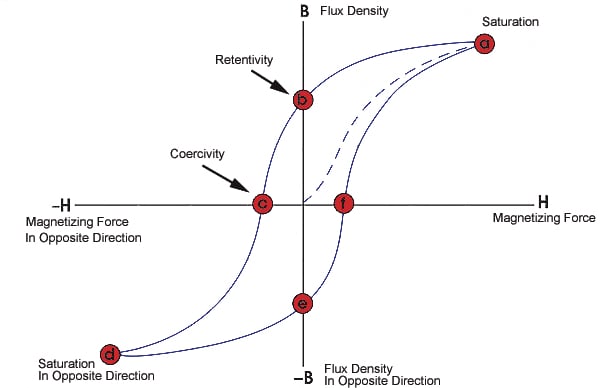
As demonstrated in the visual above, we can see that the amount of flux present in an inductor depends not only on the applied current but also on the previous state of the inductor. 

Resistance, Capacitance, and Temperature in Inductors

Ideally, inductors present only inductance, which is measured in henries (H). In the real world, however, we must content with parasitics which are always present in inductive components. Because these parasitics make an inductor’s behavior non-ideal, we can’t overlook them when simulating an inductor.

While we won’t spend much time in this article discussing the magnetic properties of inductors, here’s a list of relevant parameters that will help us improve the accuracy of our model when we simulate inductors in LTspice:

  • Rseries: Series resistance due to the finite resistivity of the copper (also known as DC resistance)
  • Rparallel: Parallel resistance caused by core losses
  • Cparallel: Capacitance of consecutive windings
  • Temperature coefficient: A consideration to account for the fact that inductors can alter their magnetic properties by self-heating (due to the current that circulates through them and parasitic resistance)

Adding these values into a simulation will help you yield more realistic results that will more closely correspond to the real-life behavior of a given inductor.

Simulation Option 1: A Simple Linear Model

A first model includes all the parameters listed above and executes a simulation as it happens in a linear circuit.

Luckily, it’s not necessary for us to add each parasitic component by hand. In order to make simulations run faster, LTspice includes internal models.

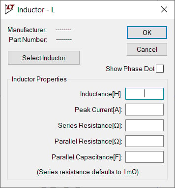
If you right-click on an inductor, you will see the following window:

Parasitic components of inductors in LTspice

Here’s a trick for LTspice! If you do not introduce any value for the parallel resistance, LTspice will include a default value. If you’d like to deactivate this option, go through the Tools menu and select the Control Panel. From here, select the Hacks! tab, as shown below.

Option for default parallel resistance (Rpar) in LTSpice
Option for default parallel resistance (Rpar) in LTspice

You’ll want to uncheck the box that says “Supply a min. inductor damping if no Rpar is given”.

Simulation Option 2: A Non-Linear Model

When linear models are not enough, LTspice provides the means to consider inductor saturation. We can define the function that determines the inductor flux.

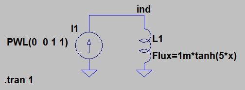
In order to define the inductor flux, we need to modify the netlist. This can be done by pressing the “CTRL” key and then right-clicking an inductor. This will bring up the following window:

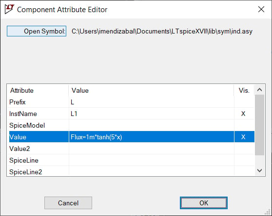
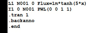
The variable “x” refers to the inductor current. We can enter our own information into the “Value” field and then press the “OK” button. Now, in order to verify our input, we select “View” in the menu and then select “SPICE Netlist”. This brings us to the schematic editor.

In our example here, our simulated circuit consists of an inductor in series with a current source.

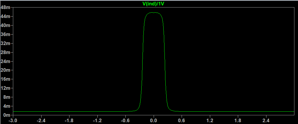
The voltage across an inductor follows can be expressed as

V=−Ldldt

So since what we are representing is the changes in the current, the inductance can be obtained directly by measuring the voltage of the inductor (node ind).

For clarity, we plot the expression: V(ind)/1V to remove voltage units. Don’t forget to set the vertical scale to linear.

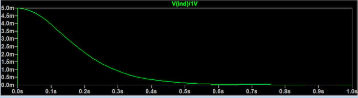
We can see why the inductance decreases in this way if we recall that the inductor’s magnetic flux is equal to inductance times current. Current increases at a steady rate during the 1-second simulation—but, because of saturation, the magnetic flux does not increase steadily. The decrease in inductance reflects this change in the relationship between current and magnetic flux. 

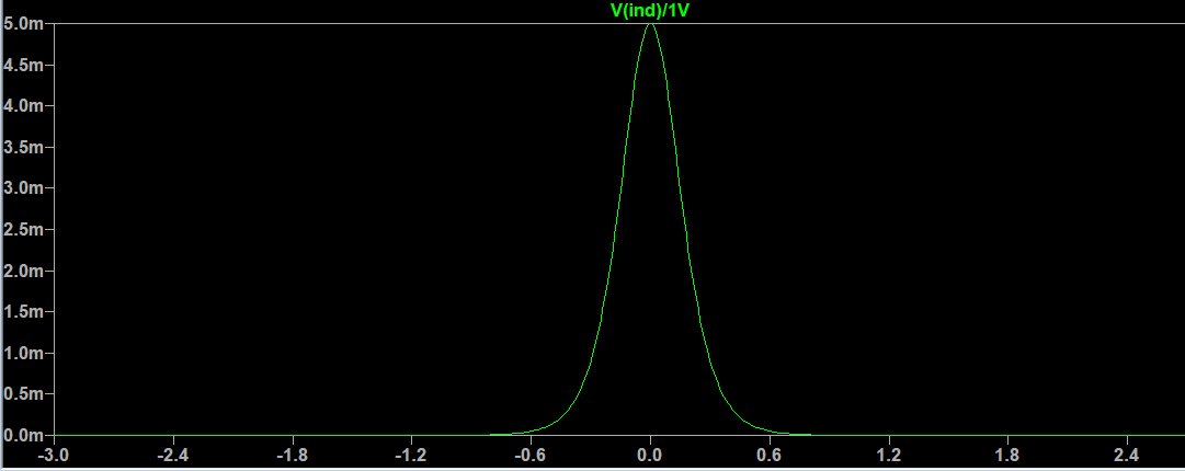
For further analysis, we can plot the inductance as a function of the current. We make the current increase from -3 amps to 3 amps in steps of 0.01.

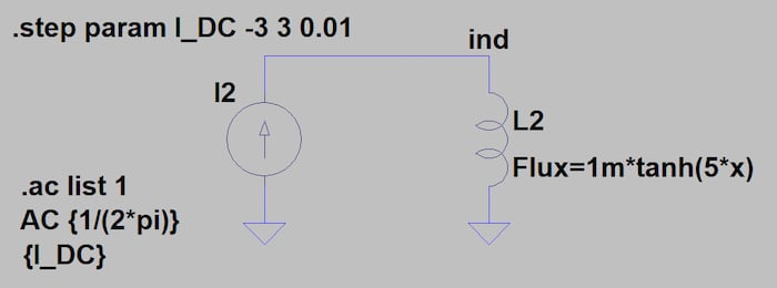
This circuit yields the following plot:

Simulation Option 3: The CHAN Model

When designing our magnetics, we need to control all the parameters of the inductors we discussed earlier. Sometimes it can be difficult to model all of them in LTspice or any other simulation tool.

There is a third model available in LTspice, the CHAN model, created by John Chan and discussed in a research paper entitled “Nonlinear transformer model for circuit simulation.” The accuracy of this model has been widely proven and it can perform the modelization of the hysteresis loop with only three parameters:

  • Coercive force (Hc), in Amp-turns/meter
  • Residual flux density (Br), in Tesla
  • Saturation flux density (Bs), in Tesla

Also, the mechanical aspects of the inductor need to be added:

  • Magnetic Length (Lm), in meters
  • Length of the gap (Lg), in meters
  • Cross-sectional area (A), in square meters
  • Number of turns (N)

Let’s see what happens to the same circuit we used before if we include all these parameters.

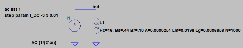
And now we plot the inductance as a function of current:

Conclusion

Inductors are complex and critical components in electronics. LTspice allows designers to make the design cycle easier by providing fast and accurate methods to simulate them. Depending on the complexity of your circuit, you can use one of the three models presented here.

The circuits in this article are quite basic, but they are a good starting point for further analysis. There is a tradeoff between speed and accuracy, but LTspice is generally quite fast, so it is always advisable to use the most precise model when possible.

Inductor Simulation with LTSpice

Related

Source: All About Circuits

Recent Posts

Bourns Releases High‑Q Air Coil Inductors for RF Aplications

29.1.2026
19

CMSE 2026 Announces Call for Presentations on High-Reliability Military and Space Electronics

28.1.2026
31

ESA Call for Papers 6th Space Passive Component Days – SPCD 2026

28.1.2026
24

Power Electronics Tools for Passives and Magnetic Designs

27.1.2026
61

Würth Elektronik Developed a Custom Transformer for Active Hand Orthosis

26.1.2026
38

Passive Components in Quantum Computing

22.1.2026
126

Exxelia Offers Custom Naval Transformers and Inductors

21.1.2026
16

Würth Elektronik Introduces Product Navigator for Passive Components

14.1.2026
89

Panasonic Passive Components for Reliable Robotic Arms

14.1.2026
115

Upcoming Events

Feb 24
16:00 - 17:00 CET

Designing Qi2 Wireless Power Systems: Practical Development and EMC Optimization

Mar 3
16:00 - 17:00 CET

Cybersecurity at the Eleventh Hour – from RED to CRA – Information and Discussion

Mar 21
All day

PSMA Capacitor Workshop 2026

View Calendar

Popular Posts

  • Buck Converter Design and Calculation

    0 shares
    Share 0 Tweet 0
  • Boost Converter Design and Calculation

    0 shares
    Share 0 Tweet 0
  • LLC Resonant Converter Design and Calculation

    0 shares
    Share 0 Tweet 0
  • Flyback Converter Design and Calculation

    0 shares
    Share 0 Tweet 0
  • Ripple Current and its Effects on the Performance of Capacitors

    3 shares
    Share 3 Tweet 0
  • How Metal Prices Are Driving Passive Component Price Hikes

    0 shares
    Share 0 Tweet 0
  • MLCC and Ceramic Capacitors

    0 shares
    Share 0 Tweet 0
  • Dual Active Bridge (DAB) Topology

    0 shares
    Share 0 Tweet 0
  • Degradation of Capacitors and its Failure Mechanisms

    0 shares
    Share 0 Tweet 0
  • What is a Dielectric Constant and DF of Plastic Materials?

    4 shares
    Share 4 Tweet 0

Newsletter Subscription


Passive Components Blog

© EPCI - Leading Passive Components Educational and Information Site

  • Home
  • Privacy Policy
  • EPCI Membership & Advertisement
  • About

No Result
View All Result
  • Home
  • Knowledge Blog
  • PCNS

© EPCI - Leading Passive Components Educational and Information Site

This website uses cookies. By continuing to use this website you are giving consent to cookies being used. Visit our Privacy and Cookie Policy.
Go to mobile version