Passive Components Blog
No Result
View All Result
  • Home
  • NewsFilter
    • All
    • Aerospace & Defence
    • Antenna
    • Applications
    • Automotive
    • Capacitors
    • Circuit Protection Devices
    • electro-mechanical news
    • Filters
    • Fuses
    • Inductors
    • Industrial
    • Integrated Passives
    • inter-connect news
    • Market & Supply Chain
    • Market Insights
    • Medical
    • Modelling and Simulation
    • New Materials & Supply
    • New Technologies
    • Non-linear Passives
    • Oscillators
    • Passive Sensors News
    • Resistors
    • RF & Microwave
    • Telecommunication
    • Weekly Digest

    Bourns Unveils Metal Powder Core High Current Low DCR Shielded Power Inductor

    Influence of Tantalum Capacitor Pellets Size on Stability During Oxide Film Formation

    Modelithics Release Discrete Components Optimization Article for RF/Microwave Designers

    Samsung Extends Capacitance of MLCC 0805 X7T 250V to 100nF

    Samtec Releases 800-Position High-Performance Array Connectors  

    DigiKey Announces Back to School Giveaway to Empower Tomorrow’s Innovators

    Ripple Steering in Coupled Inductors: SEPIC Case

    TDK Releases Low Loss Thin-Film Inductors for AI Data Centers

    Samsung Releases Ultra–High-Capacitance 4.7uF 2.5V MLCC in 0201 for AI GPU

    Trending Tags

    • Ripple Current
    • RF
    • Leakage Current
    • Tantalum vs Ceramic
    • Snubber
    • Low ESR
    • Feedthrough
    • Derating
    • Dielectric Constant
    • New Products
    • Market Reports
  • VideoFilter
    • All
    • Antenna videos
    • Capacitor videos
    • Circuit Protection Video
    • Filter videos
    • Fuse videos
    • Inductor videos
    • Inter-Connect Video
    • Non-linear passives videos
    • Oscillator videos
    • Passive sensors videos
    • Resistor videos

    Ripple Steering in Coupled Inductors: SEPIC Case

    SEPIC Converter with Coupled and Uncoupled Inductors

    Coupled Inductors in SEPIC versus Flyback Converters

    Non-Linear MLCC Class II Capacitor Measurements Challenges

    Percolation Phenomenon and Reliability of Molded Power Inductors in DC/DC converters

    Root Causes and Effects of DC Bias and AC in Ceramic Capacitors

    How to Calculate the Output Capacitor for a Switching Power Supply

    Switched Capacitor Converter Explained

    Understanding Inductor Dot Markings and Their Application in LTspice

    Trending Tags

    • Capacitors explained
    • Inductors explained
    • Resistors explained
    • Filters explained
    • Application Video Guidelines
    • EMC
    • New Products
    • Ripple Current
    • Simulation
    • Tantalum vs Ceramic
  • Knowledge Blog
  • Suppliers
    • Who is Who
  • Events
No Result
View All Result
Passive Components Blog
No Result
View All Result

NASA NEPP evaluation of T22 tantalum wet capacitors

29.5.2018
Reading Time: 3 mins read
A A

Source: Nasa nepp article

Dr. Alexander Teverovsky of ASRC Federal Space and Defense has concluded design review of the
T22 wet tantalum capacitor robustness for space applications. His “Evaluation of Series T22 Wet
Tantalum Capacitors” was recently published and is available at the following link.

RelatedPosts

Bourns Unveils Metal Powder Core High Current Low DCR Shielded Power Inductor

Influence of Tantalum Capacitor Pellets Size on Stability During Oxide Film Formation

Modelithics Release Discrete Components Optimization Article for RF/Microwave Designers

The work was performed at the NASA Goddard Space Flight Center and includes both a design review
and electrical and mechanical evaluations.

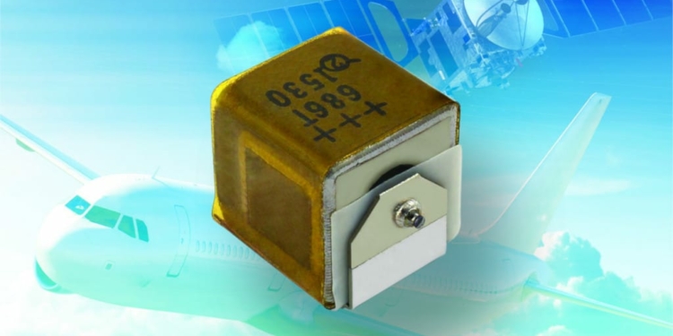
Series T22 of hermetically sealed wet tantalum capacitors (see featured image, credit: Vishay) is designed for avionics and aerospace applications and features a relatively small case size (LxWxH = 0.35×0.28×0.29) and compatibility with surface mount assembly technology.

Considering that heat release in vacuum occurs mostly by thermal conduction through the leads, this design allows using higher ripple currents in space systems. The manufacturer specifies that the part can
operate in a typical for tantalum capacitors temperature range from -55 °C to +85 °C, and to +125 °C with voltage derating.

All parts are screened by 48 hr burning-in at 85°C and rated voltage, can endure 300 thermal shock cycles, 3 V of reverse bias, 100 g mechanical shock, and 27.8 g rms of random vibration testing (RVT) per MIL-PRF-39006. Capacitors are capable of withstanding 2000 hr life testing at +85 °C and
rated voltage (VR) or at +125 °C and 2/3VR.

Key features of the T22 SMD wet tantalum capacitor:

  • Capacitance range: 10uF to 68uF
  • Voltage range: 50 V to 125V
  • Tolerance: 10 % and 20%
  • Life: 2000 hours
  • Reliability: tested to M39006 requirements
  • SMD: 9 mm x 7.1mm

Design of the parts allows using these wet electrolytic capacitors similar to regular chip tantalum capacitors, so in the following evaluations characteristics of the parts were measured similar to chip tantalum capacitors. In particular, alternative current (AC) characteristics included capacitance (C) and dissipation factor (DF) measured at 120 Hz and equivalent series resistance (ESR) measured at 100 kHz.

The parts are designed without internal Teflon sealing that is used for CLR style capacitors typically used
for space systems. This raises concerns about their hermeticity and the capability of withstanding high internal gas pressure. To address these issues, in addition to highly accelerated life testing (HALT)
at 125 °C and rated voltage, and step stress random vibration testing (RVT), the parts were evaluated by high temperature storage (2500 hr) testing at 150°C (HTS150) with measurements of electrical characteristics through the testing and the hermeticity leak rate before and after the testing. Also, the parts soldered onto printed wired boards (PWB) were stressed by 1000 temperature cycles between
-55 °C and +125 °C and their quality was assessed by additional HALT at different temperatures.
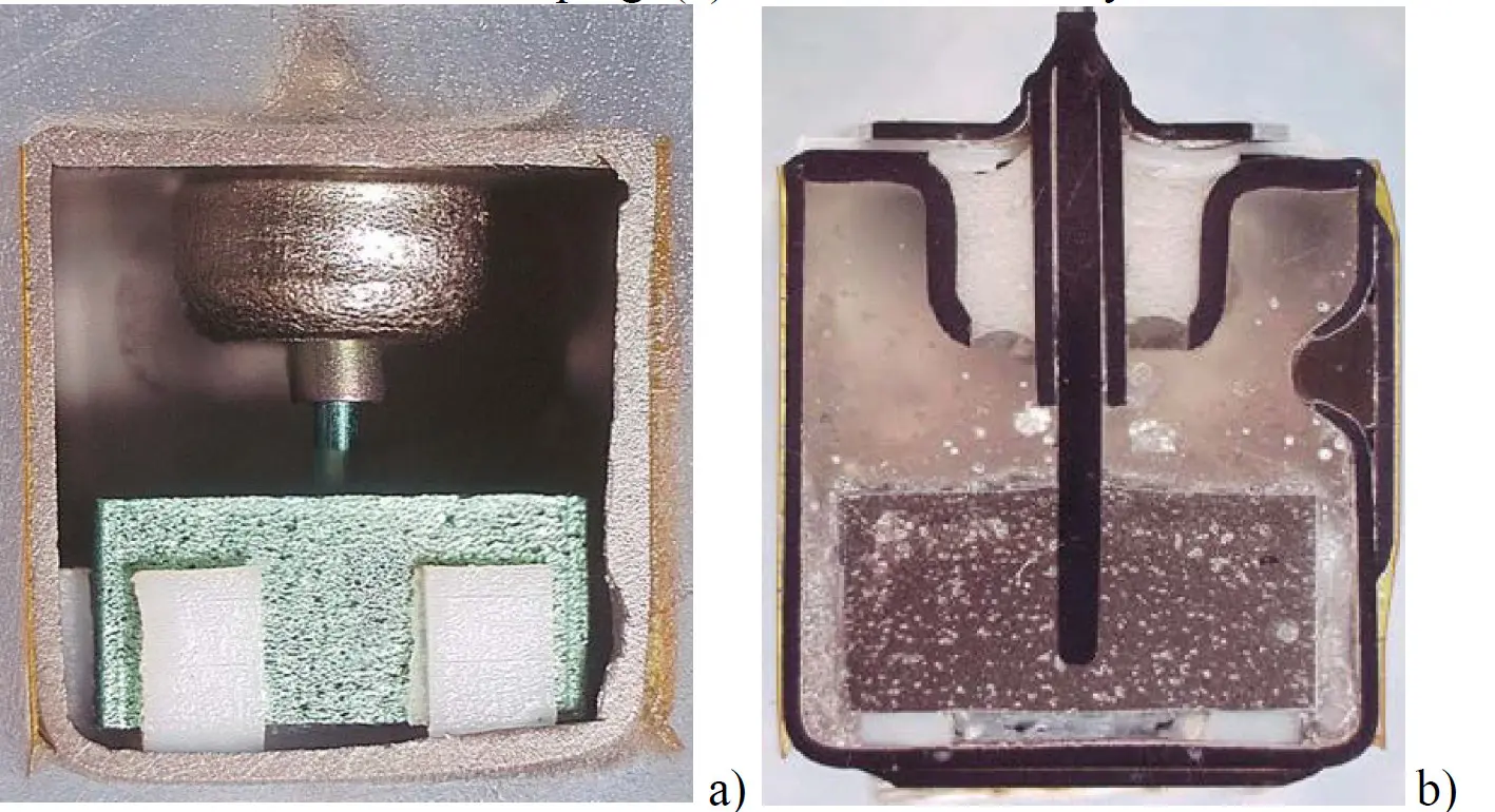
An internal (a) and cross-sectional (b) views of a 50 V capacitor. Image credit: NASA NEPP

Conclusions

Evaluation of T22 series of capacitors that included high temperature storage at 150 ºC for 2500 hours
, hermeticity leak testing, random vibration testing at different stress levels, accelerated life test
at 125 ºC, rated voltage for 770 hours, and extensive temperature cycling between -55 ºC and +125 ºC
in mounted conditions showed that the design is robust enough for space applications.

Capacitors rated to 50 V exceed the specified requirements regarding random vibration testing, accelerated life testing at conditions outside the specified limits, and temperature cycling. This part
can be used at relaxed derating requirements.

Capacitors rated to 125 V showed some anomalies during random vibration testing at 34 g rms that exceeds the specified level of 27 g rms and failed accelerated life testing at 125 ºC and rated voltage
that above the specified voltage for this temperature. This indicates much less quality margin in the design of 125 V capacitors and requires a strict enforcement of the existing derating requirements.

see the complete NASA NEPP report here.

Related

Recent Posts

Influence of Tantalum Capacitor Pellets Size on Stability During Oxide Film Formation

29.8.2025
10

Modelithics Release Discrete Components Optimization Article for RF/Microwave Designers

28.8.2025
10

Samsung Extends Capacitance of MLCC 0805 X7T 250V to 100nF

28.8.2025
12

Samsung Releases Ultra–High-Capacitance 4.7uF 2.5V MLCC in 0201 for AI GPU

27.8.2025
26

Non-Linear MLCC Class II Capacitor Measurements Challenges

19.8.2025
45

Researchers Demonstrated HfO Anti-Ferroelectric Flexible Capacitors

19.8.2025
19

High Voltage MLCCs Meeting the Growing Demand for Efficiency in Power Conversion

12.8.2025
166

Radiation Tolerance of Tantalum and Ceramic Capacitors

8.8.2025
91

TDK Releases Compact Polypropylene Film Capacitors for Resonant Topologies

7.8.2025
37

Root Causes and Effects of DC Bias and AC in Ceramic Capacitors

6.8.2025
66

Upcoming Events

Sep 3
15:30 - 17:30 CEST

How to Choose Your Magnetic Supplier

Sep 16
17:00 - 18:00 CEST

EMI Shielding Challenges

Sep 22
September 22 @ 13:00 - September 25 @ 15:15 EDT

Pre Cap Visual Inspection per Mil-Std-883 (TM 2017)

Sep 30
September 30 @ 12:00 - October 2 @ 14:00 EDT

MIL-Std-883 TM 2010

Oct 17
12:00 - 14:00 EDT

External Visual Inspection per MIL-STD-883 TM 2009

View Calendar

Popular Posts

  • Buck Converter Design and Calculation

    0 shares
    Share 0 Tweet 0
  • Boost Converter Design and Calculation

    0 shares
    Share 0 Tweet 0
  • Flyback Converter Design and Calculation

    0 shares
    Share 0 Tweet 0
  • LLC Resonant Converter Design and Calculation

    0 shares
    Share 0 Tweet 0
  • What is a Dielectric Constant and DF of Plastic Materials?

    4 shares
    Share 4 Tweet 0
  • Ripple Current and its Effects on the Performance of Capacitors

    3 shares
    Share 3 Tweet 0
  • Dual Active Bridge (DAB) Topology Explained

    0 shares
    Share 0 Tweet 0
  • How to Design an Inductor

    0 shares
    Share 0 Tweet 0
  • Core Materials, Permeability and Their Losses

    0 shares
    Share 0 Tweet 0
  • MLCC Case Sizes Standards Explained

    0 shares
    Share 0 Tweet 0

Newsletter Subscription


Passive Components Blog

© EPCI - Leading Passive Components Educational and Information Site

  • Home
  • Privacy Policy
  • EPCI Membership & Advertisement
  • About

No Result
View All Result
  • Home
  • Knowledge Blog
  • Premium Suppliers

© EPCI - Leading Passive Components Educational and Information Site

This website uses cookies. By continuing to use this website you are giving consent to cookies being used. Visit our Privacy and Cookie Policy.
Go to mobile version