Passive Components Blog
No Result
View All Result
  • Home
  • NewsFilter
    • All
    • Aerospace & Defence
    • Antenna
    • Applications
    • Automotive
    • Capacitors
    • Circuit Protection Devices
    • electro-mechanical news
    • Filters
    • Fuses
    • Inductors
    • Industrial
    • Integrated Passives
    • inter-connect news
    • Market & Supply Chain
    • Market Insights
    • Medical
    • Modelling and Simulation
    • New Materials & Supply
    • New Technologies
    • Non-linear Passives
    • Oscillators
    • Passive Sensors News
    • Resistors
    • RF & Microwave
    • Telecommunication
    • Weekly Digest

    Transformer Safety IEC 61558 Standard

    ESR of Capacitors, Measurements and Applications

    Murata Christophe Pottier Appointed President of EPCIA

    3-Phase EMI Filter Design, Simulation, Calculation and Test

    YAGEO Unveils Compact 2.4 GHz SMD Antenna

    KYOCERA AVX Releases Antenna for Iridium Satellite IoT Applications

    Molex Releases Industry-First Quad-Row Board-to-Board Connectors with EMI Shields

    Image credit: Samtec

    How to Match the Right Connector with Protocol Requirements

    Smoltek CNF-MIM Capacitors Pass 1,000h Reliability Test

    Trending Tags

    • Ripple Current
    • RF
    • Leakage Current
    • Tantalum vs Ceramic
    • Snubber
    • Low ESR
    • Feedthrough
    • Derating
    • Dielectric Constant
    • New Products
    • Market Reports
  • VideoFilter
    • All
    • Antenna videos
    • Capacitor videos
    • Circuit Protection Video
    • Filter videos
    • Fuse videos
    • Inductor videos
    • Inter-Connect Video
    • Non-linear passives videos
    • Oscillator videos
    • Passive sensors videos
    • Resistor videos

    Transformer Safety IEC 61558 Standard

    3-Phase EMI Filter Design, Simulation, Calculation and Test

    Transformer Design Optimization for Power Electronics Applications

    Common Mode Chokes Selection for RF Circuits in Next-Generation Communication Systems

    Capacitor Self-balancing in a Flying-Capacitor Buck Converter

    How to Select Ferrite Bead for Filtering in Buck Boost Converter

    Power Inductors Future: Minimal Losses and Compact Designs

    Percolation Phenomenon: Degradation of Molded Power Inductors in DC/DC Converters

    Connector PCB Design Challenges

    Trending Tags

    • Capacitors explained
    • Inductors explained
    • Resistors explained
    • Filters explained
    • Application Video Guidelines
    • EMC
    • New Products
    • Ripple Current
    • Simulation
    • Tantalum vs Ceramic
  • Knowledge Blog
  • Suppliers
    • Who is Who
  • PCNS
    • PCNS 2025
    • PCNS 2023
    • PCNS 2021
    • PCNS 2019
    • PCNS 2017
  • Events
No Result
View All Result
Passive Components Blog
No Result
View All Result

New Whiskers Phenomena?

26.10.2020
Reading Time: 8 mins read
A A

Source: EPCI e-Symposium PCNS paper

by Jean Pascal Michelet and Jean Edmond Le Calvé
VALEO Créteil, France

RelatedPosts

Transformer Safety IEC 61558 Standard

ESR of Capacitors, Measurements and Applications

Murata Christophe Pottier Appointed President of EPCIA

submitted to the 2nd PCNS 10-13th September 2019, Bucharest, Romania as paper 4.4.

Introduction

Some PCBAs were submitted to a whisker test +85°C 85% RH for 200h duration and additional 2h from +85°C/85% RH-T° +25°C/50% RH 5 Cycles. The functional test pass and boards were sent to an external lab for visual inspection. Inspection failed because of Tin whiskers detected on MLCCs terminations.

As reminder a whisker is a spontaneous columnar or cylindrical filament, usually of monocrystalline metal, emanating from the surface of a finish. In automotive electronic the most common are Tin Whiskers growing on Tin platted Copper surfaces. Our suppliers delivering components with Tin or Tin alloy finishes, if no whiskers mitigation method is used or efficiency demonstrated, should perform whisker tests according to JESD-201 standard / 22A121 method [1] [2].

As many Multi-Layer-Ceramic-Capacitors (MLCCs) got whiskers, we returned to the Bill of Material (BOM) and traceability to find out exactly the part numbers. We went back to their qualifying and the results were good. We also checked the Process Change Notification (PCN) history to see if the suppliers submitted any PCN relative to the termination scheme and we did not find any on this topic. Moreover, all the impacted MLCCs got a Nickel barrier between Copper electrode and Nickel platting supposed to avoid or limit the Tin whiskers growth.

Observations

Fig 1: Observations of the whiskers

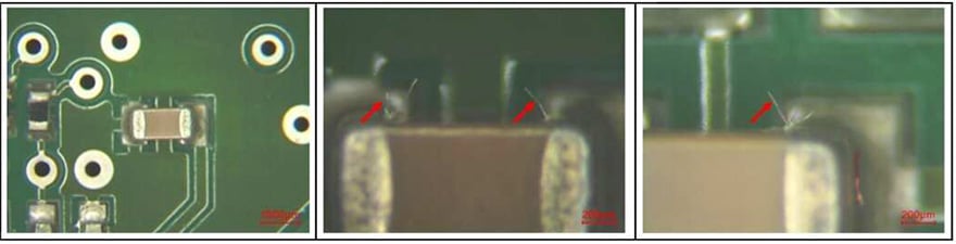
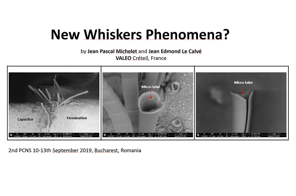
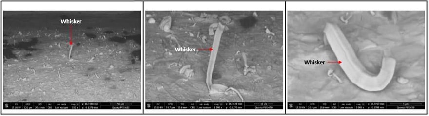
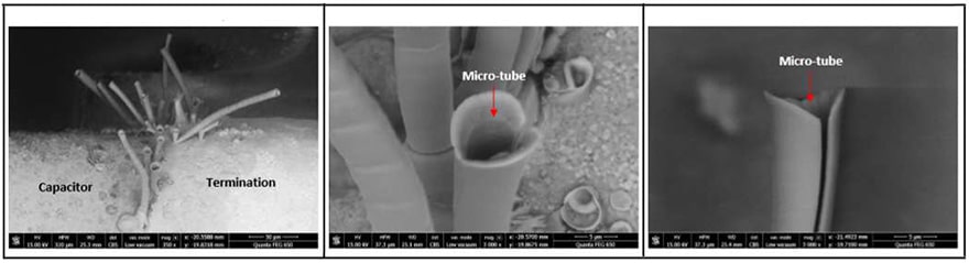
Observations of the whiskers: Lengths are measured up to 225μm. Whiskers have tubular shapes. They are located on the sides only, never on the top (not possible to observe the bottom). Whiskers are located between the Tin platted termination and the flux rise.

The shape of these whiskers is not conventional and is not described neither by the NASA [3] nor by JEDEC [2]. Some hollow whiskers were reported [4], [5], We did not find any document on Tubular whiskers growth on Electronic components. For us it is the first observation of such structure.


Fig2: EDX analysis evidenced Tin, Bromide, Barium and Oxygen. Barium is coming for the BaTiO3 ceramic from X7R
MLCC. Bromide origin is unknown


Fig3: The shape of “standard” Whiskers was observed on another component terminal and compared with those found
on the MLCCs


Fig4: The whiskers in question are hollow like micro-tubes. They are transparent and very brittle


Fig5: The micro-tubes are like bamboo canes with a succession of segments. Some have their end slit on the side

Root Cause Analysis

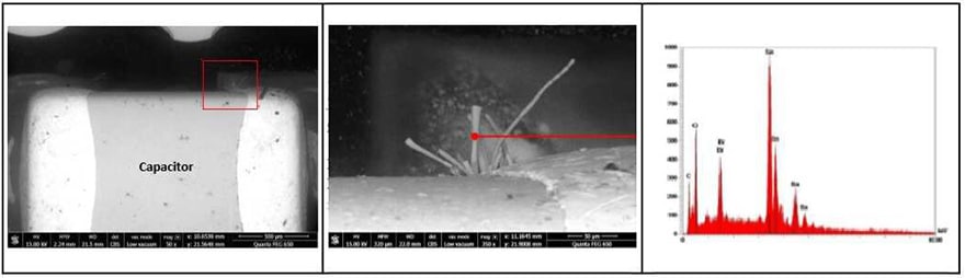
A cross section was done in the horizontal plane of a MLCC at the maximum flux rise where the Whiskers grow.


Fig6: The extremity of the termination evidenced Tin over Nickel and Copper. Tin is partially oxidized (grey color) like
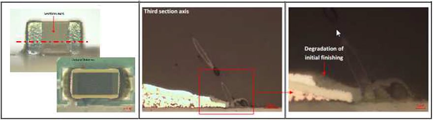
whiskers. In the section plan the tubular shape is evidenced. Whiskers growth is on the ceramic nearby or in contact
with the Tin edge of Tin layer


Fig7: The edge of the Tin layer is oxidized by Bromide. The crack between the ceramic and the termination is a minor
polishing artefact. Bromide origin was identified as coming from the Solder Flux

Risk Analysis

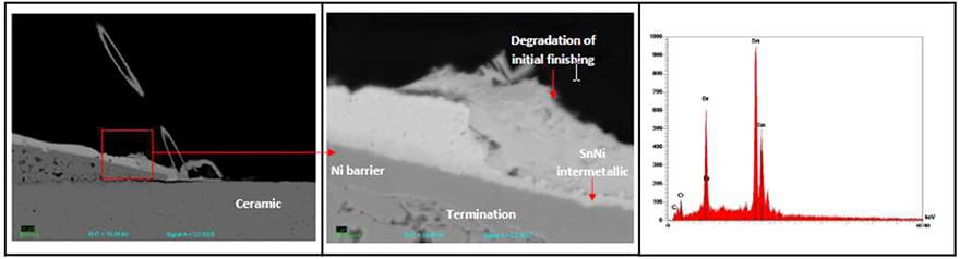
The major risk of metallic whisker is to reduce the insulation distance or worst to make a short circuit. In our case the whiskers is made of Tin, Oxygen and Bromide. The visual observation evidenced transparent tubular structure, so it is not a pure metal, but a compound of Tin oxide + Bromide.

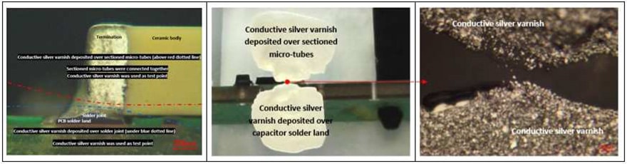
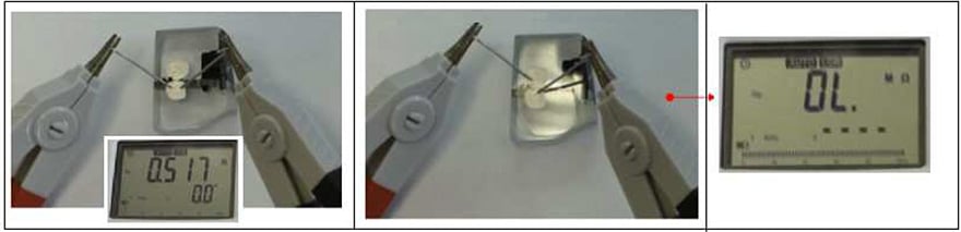
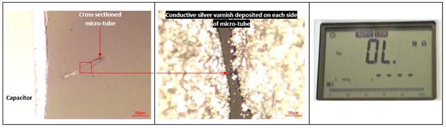
Tin oxide is classified as wide band gap (3.6 eV) N-type semiconductor. Considering the risk to have a conductive path, we make electrical verification. We did several attempts to contact the Whiskers by probing but it failed because of whiskers are too brittle. We used a cross section through both MLCC termination solder and some whiskers ends to be contacted with Silver epoxy ink.


Fig8: cross section in the vertical plan contacting the MLCC solder and the whiskers ends. Both were contacted with silver epoxy. The realization of the micro-section as much as the precise deposit of the silver lacquer are difficult to achieve.


Fig9: Verification of the contact, and measure 2 probes. The whiskers are not conductive (or not contacted). A verification was done by contacting both ends of a single whiskers.


Fig10: Verification of the whiskers resistance done by contacting both ends of a single whiskers: not conductive

Tin tubes growth hypothesis

While lowering the reflow temperature profile, more hollow whiskers were possible to be generated. This suggests that the SnO hollow whiskers growth mechanism is promoted by some still active flux residues not fully desactivated by the reflow process. Among these residues the weak organic acids (WOA) and halogen/bromine are suspected to contribute to the growth mechanism of SnO whisker.

Tin hydroxide chloride [Sn3O2(OH)2-xClx] was reported to be intermediate corrosion products on reaction from Sn to SnO/SnO2 (depending on pH and presence of chlorine halogen) [7]. A similar Tin hydroxide bromide could have been the intermediate corrosion product to give rise to the tin oxide hollow whisker encountered:


Fig11: corrosion of Tin layer with intermediate Tin hydroxide halogen [7]

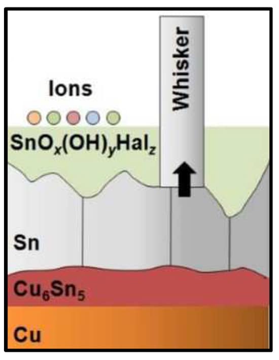
This localized corrosion process in presence of halogen ion (bromine) could have been at the origin of the tube shape observed. The transformation of Tin nanowires to amorphous oxide nanotubes has been described by HoSun Shin [8] based on a localized corrosion process in an aqueous solution involving hydrochloric acids (from halogen chlorine ion). The nano-tubes were formed by the dissolution of the tin atoms in the core of the “nanowire” while the tin oxide shell was remaining.

Conclusion

Hollow Tin Wiskers are transparent, very brittle and not conductive.

We demonstrated no risk of leakage or short circuit. At visual inspection they can be considered as cosmetic.

Growth mechanism is supected to come from a localized corrosion process by a Bromine acidic solution from the Solder flux residues and the moisture from the humid atmosphere of the damp heat test.

References

1) JEDEC STANDARD JESD22-A121A “Test Method for Measuring Whisker Growth on Tin and Tin Alloy Surface Finishes”, July 2008.
2) JEDEC STANDARD JESD201A “Environmental Acceptance Requirements for Tin Whisker Susceptibility of Tin and Tin Alloy Surface Finishes”, Sept. 2008.
3) Jay A. Brusse, Gary J. Ewell, and Jocelyn P. Siplon, “Tin Whiskers: Attributes and Mitigation”, CARTS 2002: 22nd Capacitor and Resistor Technology Symposium, 25-29 March 2002
4) H. Kehrer and H. Kadereit, “Tracer Experiments on the Growth of Tin Whiskers,” Applied Physics Letters, 16, no. 11, pp. 411-412, June 1, 1970.
5) Jing Cheng, Paul T. Vianco, and James C.M. Li, “Hollow tin/chromium whiskers”, Applied Physics Letters, 96, 184102, 2010.
6) David Hillman, “False tin-whiskers – beware of masquerading tin-copper intermetallics”, ITRI, 2012
7) Pierre Eckold, “Corrosion of Tin and its Influence on Whisker Growth”, 7th IPC–CALCE International ymposium on Tin Whiskers, November 12-13, 2013.
8) Ho SunShin, Seong GiJeon, JinYu, Jae YongSong, “Transformation of Sn nanowires to oxide nanotubes by a localized corrosion process”, Materials Letters Volume 82, 1 September 2012.

Acknowledgements

Special Thanks to José Gomes from ILED. Investigation Laboratory for Electronic Devices Site Montesquieu 8 Allée Isaac Newton 33650 Martillac-France


more 2nd PCNS symposium technical papers can be viewed and downloaded in pdf from EPCI Academy e-Proceedings:

Related

Recent Posts

ESR of Capacitors, Measurements and Applications

7.11.2025
14

3-Phase EMI Filter Design, Simulation, Calculation and Test

6.11.2025
25

Smoltek CNF-MIM Capacitors Pass 1,000h Reliability Test

6.11.2025
9

Capacitor Lead Times: October 2025

6.11.2025
52

Paumanok Unveils Aluminum Capacitor Foils World Markets Study 2025-2030

6.11.2025
13

Coilcraft Introduces Ultra-Low Loss Shielded Power Inductors

6.11.2025
13

Murata Expands High Cutoff Frequency Chip Common Mode Chokes

5.11.2025
9

Microhardness — the Hidden Key to Understanding MnOx Cathode Quality in Tantalum Capacitors

3.11.2025
24

Samsung to Invest in its Philippine MLCC Facility to Meet Automotive Demand

3.11.2025
32

Lightweight Model for MLCC Appearance Defect Detection

3.11.2025
25

Upcoming Events

Nov 11
17:00 - 18:00 CET

Industrial Applications Demand More from Interconnects in Next-Gen Designs

Nov 12
11:00 - 12:00 CET

PCB Design: Impedance is for everyone!

Nov 12
November 12 @ 12:00 - November 13 @ 14:15 EST

Microelectronic Packaging Failure Modes and Analysis

View Calendar

Popular Posts

  • Buck Converter Design and Calculation

    0 shares
    Share 0 Tweet 0
  • Boost Converter Design and Calculation

    0 shares
    Share 0 Tweet 0
  • LLC Resonant Converter Design and Calculation

    0 shares
    Share 0 Tweet 0
  • Flyback Converter Design and Calculation

    0 shares
    Share 0 Tweet 0
  • Ripple Current and its Effects on the Performance of Capacitors

    3 shares
    Share 3 Tweet 0
  • MLCC and Ceramic Capacitors

    0 shares
    Share 0 Tweet 0
  • Dual Active Bridge (DAB) Topology

    0 shares
    Share 0 Tweet 0
  • What is a Dielectric Constant and DF of Plastic Materials?

    4 shares
    Share 4 Tweet 0
  • SEPIC Converter Design and Calculation

    0 shares
    Share 0 Tweet 0
  • Flying Capacitors

    0 shares
    Share 0 Tweet 0

Newsletter Subscription


Passive Components Blog

© EPCI - Leading Passive Components Educational and Information Site

  • Home
  • Privacy Policy
  • EPCI Membership & Advertisement
  • About

No Result
View All Result
  • Home
  • Knowledge Blog
  • PCNS

© EPCI - Leading Passive Components Educational and Information Site

This website uses cookies. By continuing to use this website you are giving consent to cookies being used. Visit our Privacy and Cookie Policy.
Go to mobile version