Passive Components Blog
No Result
View All Result
  • Home
  • NewsFilter
    • All
    • Aerospace & Defence
    • Antenna
    • Applications
    • Automotive
    • Capacitors
    • Circuit Protection Devices
    • electro-mechanical news
    • Filters
    • Fuses
    • Inductors
    • Industrial
    • Integrated Passives
    • inter-connect news
    • Market & Supply Chain
    • Market Insights
    • Medical
    • Modelling and Simulation
    • New Materials & Supply
    • New Technologies
    • Non-linear Passives
    • Oscillators
    • Passive Sensors News
    • Resistors
    • RF & Microwave
    • Telecommunication
    • Weekly Digest

    Developing Low Inductance Film Capacitor using Bode 100 Analyzer

    Highly Reliable Flex Rigid PCBs, Würth Elektronik Webinar

    Würth Elektronik Releases High Performance TLVR Coupled Inductors

    YAGEO Extends Rectangular Aluminum Electrolytic Capacitor Family

    Dr. Tomas Zednicek Vision for Europe 2025 Passive Electronics Market

    Littelfuse Releases Industry-First SMD Fuse with 1500A Interrupting Rating at 277V

    TDK Unveils Industry Highest Rated Current Multilayer Chip Beads

    Vishay Releases Automotive SMD Thick Film Power Resistor for Enhanced Protection Against Short Transient Pulses

    Exxelia Power Film Capacitors Support Critical Systems Across Various Industries

    Trending Tags

    • Ripple Current
    • RF
    • Leakage Current
    • Tantalum vs Ceramic
    • Snubber
    • Low ESR
    • Feedthrough
    • Derating
    • Dielectric Constant
    • New Products
    • Market Reports
  • VideoFilter
    • All
    • Antenna videos
    • Capacitor videos
    • Circuit Protection Video
    • Filter videos
    • Fuse videos
    • Inductor videos
    • Inter-Connect Video
    • Non-linear passives videos
    • Oscillator videos
    • Passive sensors videos
    • Resistor videos

    Highly Reliable Flex Rigid PCBs, Würth Elektronik Webinar

    Causes of Oscillations in Flyback Converters

    How to design a 60W Flyback Transformer

    Modeling and Simulation of Leakage Inductance

    Power Inductor Considerations for AI High Power Computing – Vishay Video

    Coupled Inductors in Multiphase Boost Converters

    VPG Demonstrates Precision Resistor in Cryogenic Conditions

    Comparison Testing of Chip Resistor Technologies Under High Vibration

    EMC Challenges for High Speed Signal Immunity and Low EMI

    Trending Tags

    • Capacitors explained
    • Inductors explained
    • Resistors explained
    • Filters explained
    • Application Video Guidelines
    • EMC
    • New Products
    • Ripple Current
    • Simulation
    • Tantalum vs Ceramic
  • Knowledge Blog
  • Suppliers
    • Who is Who
  • Events
No Result
View All Result
Passive Components Blog
No Result
View All Result

RF Transformer Explained

27.11.2019
Reading Time: 2 mins read
A A

Source: RF Design article

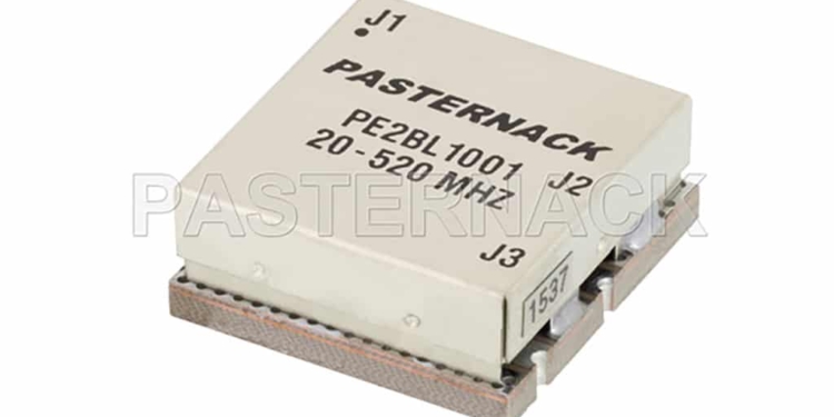
RF Transformers are two, or more, port passive devices with a wide range of uses for many RF applications. One of the most common uses of an RF transformer is the Balun, which provides efficient coupling between unbalanced transmission circuits and balanced circuits. Other common uses are for impedance matching between circuits of different impedances. Other applications include DC isolation, injecting DC current, or enhancing the common mode rejection of a circuit.

RelatedPosts

Integrated Bulk Acoustic Wave (BAW) Technology Explained – Texas Instruments and Mouser Electronics EE Journal Chalk Talk Video

Würth Elektronik Introduces Robust, Resilient, Mountable Radio Interference Suppression Choke

What is RFID? How RFID works? RFID Explained in Detail

RF transformers function via the mechanism of magnetically coupling between conductors structured in such a way to provide the desired function. There are a wide range of RF transformer technologies, including core & wire, transmission line, low temperature co-fired ceramic (LTCC), and monolithic microwave integrated circuit (MMIC), and transformers are built differently depending on the technology. For instance, the original transformer technology was core & wire, where two insulated conductors were wrapped around a ferromagnetic or air core.

With a core & wire transformer, magnetic flux developed within the core by injecting an alternating current through one of the conductive paths results in a current in the secondary path. The ratio of the number of turns around the core determines the extent of the impedance transformation from one side of the transformer to the other. In this case, the performance of the RF transformer is dictated largely by the properties of the core material used. For example, if a ferromagnetic core is used, the core’s magnetic behavior is dependent on the temperature, frequency, and power of signals passing through it. Hence, careful selection of core material and transformer fabrication practices are necessary to realize optimal transformer performance.

Transformers can also be made by wrapping transmission lines around ferromagnetic or air cores. Moreover, quarter-wave lengths of transmission lines can also be used to build another type of RF transformer. LTCC and MMIC RF transformers are fabricated using planar conductors and insulative layers to develop very high frequency RF transformers in compact form factors. As the physical size of an RF transformer greatly influences the RF performance parameters, LTCC and MMIC RF transformers typically exhibit poor low frequency performance compared to physically larger core & wire and transmission line transformers.

Common RF Transformer Applications

  • Impedance transformation (i.e. impedance matching)
  • Efficiently coupling balanced to unbalanced circuits
  • Voltage transformation
  • Providing DC isolation between circuits
  • Injecting DC current into an RF path
  • Enhancing common mode rejection (CMR)
  • Ground isolation
  • Filtering high frequency signals from a signal line

featured image source: Pasternack


Related

Recent Posts

Würth Elektronik Releases High Performance TLVR Coupled Inductors

15.5.2025
7

Causes of Oscillations in Flyback Converters

15.5.2025
6

TDK Unveils Industry Highest Rated Current Multilayer Chip Beads

14.5.2025
13

How to design a 60W Flyback Transformer

12.5.2025
21

Murata Releases 008004 High-Frequency SMD Chip Inductor

12.5.2025
21

Modeling and Simulation of Leakage Inductance

9.5.2025
19

Power Inductor Considerations for AI High Power Computing – Vishay Video

9.5.2025
27

TAIYO YUDEN Releases Compact SMD Power Inductors for Automotive Application

9.5.2025
17

KYOCERA AVX Releases Compact High-Directivity Couplers

7.5.2025
24

YAGEO Releases High Current SMD Common Mode Choke With Shape Core Construction

5.5.2025
28

Upcoming Events

May 28
16:00 - 17:00 CEST

Power Over Data Line

View Calendar

Popular Posts

  • Buck Converter Design and Calculation

    0 shares
    Share 0 Tweet 0
  • Boost Converter Design and Calculation

    0 shares
    Share 0 Tweet 0
  • What is a Dielectric Constant and DF of Plastic Materials?

    4 shares
    Share 4 Tweet 0
  • LLC Resonant Converter Design and Calculation

    0 shares
    Share 0 Tweet 0
  • Flyback Converter Design and Calculation

    0 shares
    Share 0 Tweet 0
  • MLCC Case Sizes Standards Explained

    0 shares
    Share 0 Tweet 0
  • Flying Capacitors Explained

    0 shares
    Share 0 Tweet 0
  • YAGEO Extends Rectangular Aluminum Electrolytic Capacitor Family

    0 shares
    Share 0 Tweet 0
  • Ripple Current and its Effects on the Performance of Capacitors

    3 shares
    Share 3 Tweet 0
  • Dual Active Bridge (DAB) Topology Explained

    0 shares
    Share 0 Tweet 0

Newsletter Subscription


Passive Components Blog

© EPCI - Leading Passive Components Educational and Information Site

  • Home
  • Privacy Policy
  • EPCI Membership & Advertisement
  • About

No Result
View All Result
  • Home
  • Knowledge Blog
  • Premium Suppliers

© EPCI - Leading Passive Components Educational and Information Site

This website uses cookies. By continuing to use this website you are giving consent to cookies being used. Visit our Privacy and Cookie Policy.
Go to mobile version