Passive Components Blog
No Result
View All Result
  • Home
  • NewsFilter
    • All
    • Aerospace & Defence
    • Antenna
    • Applications
    • Automotive
    • Capacitors
    • Circuit Protection Devices
    • electro-mechanical news
    • Filters
    • Fuses
    • Inductors
    • Industrial
    • Integrated Passives
    • inter-connect news
    • Market & Supply Chain
    • Market Insights
    • Medical
    • Modelling and Simulation
    • New Materials & Supply
    • New Technologies
    • Non-linear Passives
    • Oscillators
    • Passive Sensors News
    • Resistors
    • RF & Microwave
    • Telecommunication
    • Weekly Digest

    Vishay Extends Aluminum Capacitors Rating Up to 600 V for DC Links

    Würth Elektronik Introduces Product Navigator for Passive Components

    Panasonic Passive Components for Reliable Robotic Arms

    Littelfuse Unveils Ultra-Low-Power TMR Magnetic Switches

    DC/DC Push‑Pull Converter vs PSFB Design Guide

    Wk 2 Electronics Supply Chain Digest

    Rubycon PMLCAP DC‑Link Film Capacitors in Mass Production

    Bourns SSD‑1000A AEC‑Q Digital Current Sensors

    YAGEO High‑Capacitance X7R Automotive MLCC Extensions

    Trending Tags

    • Ripple Current
    • RF
    • Leakage Current
    • Tantalum vs Ceramic
    • Snubber
    • Low ESR
    • Feedthrough
    • Derating
    • Dielectric Constant
    • New Products
    • Market Reports
  • VideoFilter
    • All
    • Antenna videos
    • Capacitor videos
    • Circuit Protection Video
    • Filter videos
    • Fuse videos
    • Inductor videos
    • Inter-Connect Video
    • Non-linear passives videos
    • Oscillator videos
    • Passive sensors videos
    • Resistor videos

    One‑Pulse Characterization of Nonlinear Power Inductors

    Thermistor Linearization Challenges

    Coaxial Connectors and How to Connect with PCB

    PCB Manufacturing, Test Methods, Quality and Reliability

    Transformer Behavior – Current Transfer and Hidden Feedback

    Choosing the Right Capacitor: The Importance of Accurate Measurements

    RF Inductors: Selection and Design Challenges for High-Frequency Circuits

    Transformer Safety IEC 61558 Standard

    3-Phase EMI Filter Design, Simulation, Calculation and Test

    Trending Tags

    • Capacitors explained
    • Inductors explained
    • Resistors explained
    • Filters explained
    • Application Video Guidelines
    • EMC
    • New Products
    • Ripple Current
    • Simulation
    • Tantalum vs Ceramic
  • Knowledge Blog
  • Suppliers
    • Who is Who
  • PCNS
    • PCNS 2025
    • PCNS 2023
    • PCNS 2021
    • PCNS 2019
    • PCNS 2017
  • Events
No Result
View All Result
Passive Components Blog
No Result
View All Result

RLC Circuit Switching Response Explained

2.5.2025
Reading Time: 8 mins read
A A

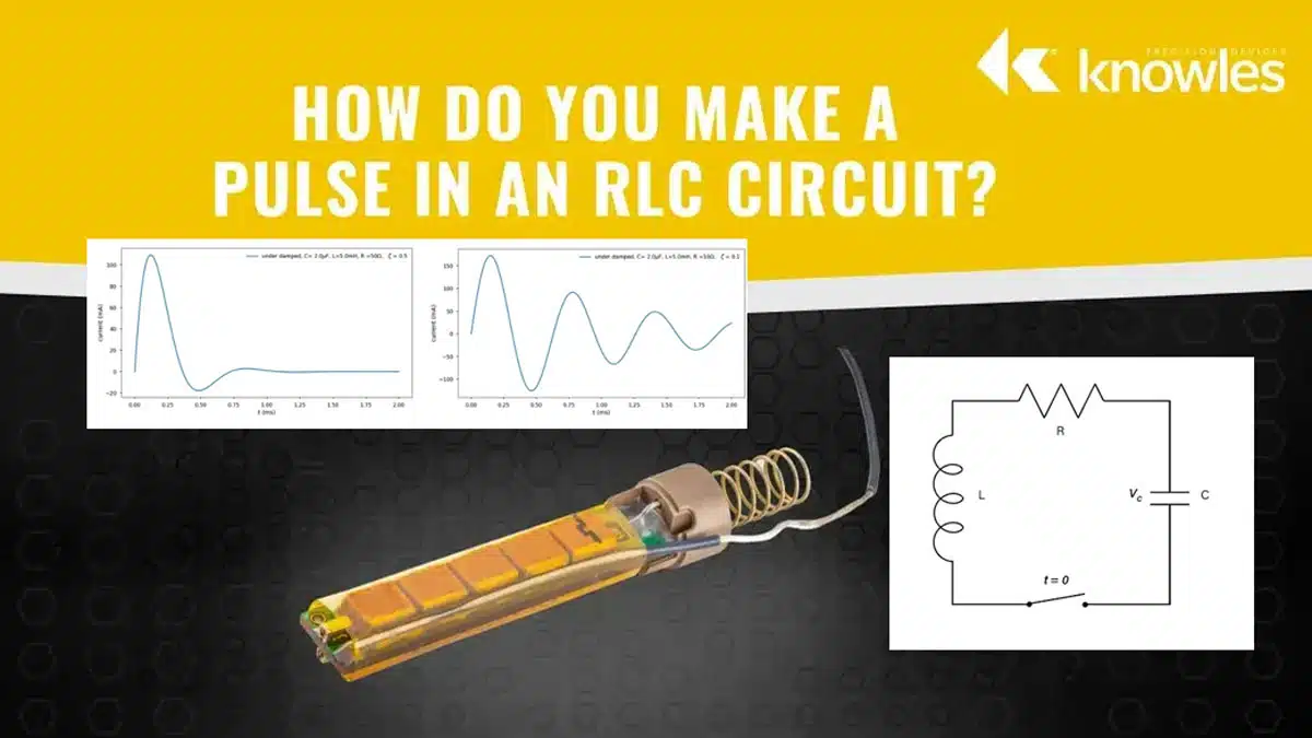
This article based on Knowles Precision Devices blog explains how an RLC circuit responds to a switching pulse.

One of the fundamental roles of capacitors is charging and discharging energy predictably. Many electronics applications leverage capacitors to store energy and release it in a controlled pulse of current or voltage. Here, we’ll revisit how pulses are produced in a basic RLC circuit featuring a capacitor (C), inductor (L) and resistor (R). 
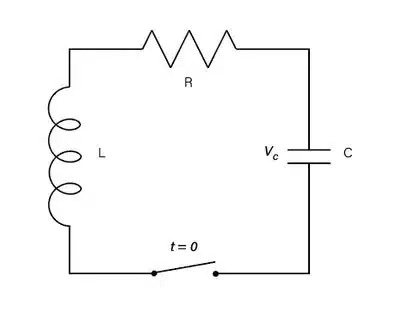
RelatedPosts

Knowles Doubles Capacitance of its Class I Ceramic C0G Capacitors

Knowles Releases High Q Non-Magnetic X7R MLCCs for Medical Imaging

Knowles Unveils High-Performance Safety-Certified MLCC Capacitors

Series RLC Circuit

As mentioned above, a series RLC circuit, show in Figure 1, is made up of the three most common passive components in electronics engineering. When the capacitor is charged to an initial voltage (V0) and switched to discharge via the resistor and inductor (I0=0), three types of responses can occur depending on the component values involved.

Figure 1. Series RLC circuit with a switch

When assessing current in an RLC circuit, damping dictates which equation you should use to determine how current varies over time. Is the system overdamped, critically damped or underdamped? The damping ratio, ζ, places a system into one of these categories. 

Two RLC circuit parameters can be used to understand a system’s damping ratio: neper frequency and resonant angular frequency.
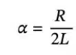
Neper Frequency 

The neper frequency refers to an exponential transience rate. In other words, how quickly is energy lost from the system?

Find the neper frequency α using: 

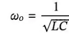
Resonant Angular Frequency 

The resonant angular frequency ω0 indicates what frequency a system will oscillate at: 

In combination, these parameters can be used to calculate the damping factor and identify which mathematical model would best represent the system’s behavior. 

Damping Factor 

Refocusing on the damping factor, the value for ζ places the system into one of three categories. There are three cases to consider: 

Case 1: Overdamped: ζ > 1 

Case 2: Critically Damped: ζ = 1 

Case 3: Under Damped: ζ < 1 
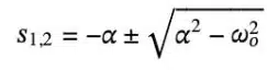
where:

Capacitor Discharge Current Theory derives solutions for current over time for each damping case. Here, we’ll leverage those results for the sake of example. 

Case 1: Overdamped Current Response 

When ζ > 1, apply the following equation: 
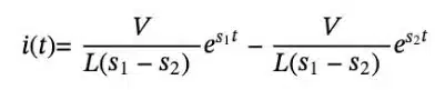
where:

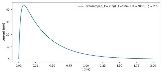
To observe an overdamped response, shown in Figure 2, charge the capacitor to 10V and set C to 2.0μF, L to 5.0mH and R to 200Ω.

Figure 2. Current over time for an overdamped RLC circuit

Case 2: Critically Damped Current Response Case 3: Underdamped Current Response 

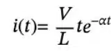
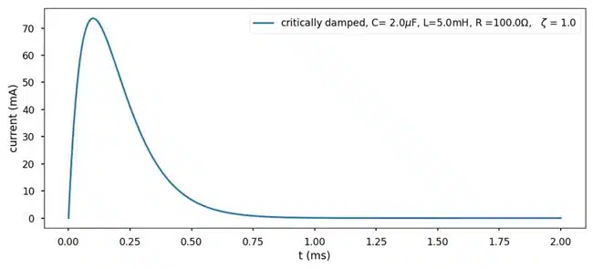
When ζ = 1, apply the following equation: 

To observe a critically damped response, shown in Figure 3, keep C and L the same and set R to 100Ω. As shown, critically damped cases typically have higher peak amplitudes than overdamped cases. 

Figure 3. Current over time for an underdamped RLC circuit

Case 3: Underdamped Current Response 

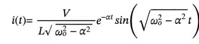
When ζ < 1, apply the following equation: 

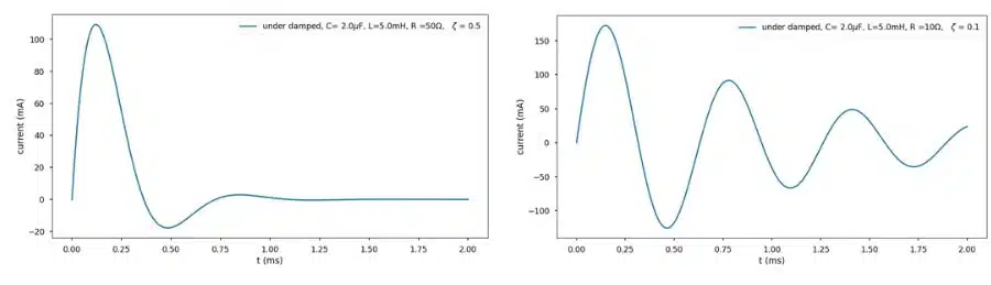
To observe an underdamped response, shown in Figure 4, keep C and L the same and set R to 50Ω. With all over variables remaining constant over time, resistance drives damping. As resistance decreases, the damping ratio decreases and peaks get larger. In this case, oscillation and decay, a pair known as ringing, become more pronounced too. The damping ratio determines the rate at which decay occurs.  

Figure 4: Current over time for an underdamped circuit with 50Ω resistance (left) vs. 10Ω resistance (right) 

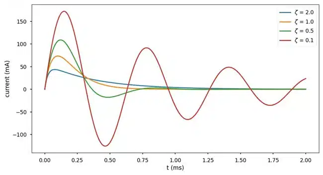
Peak current varies among damping cases, which is best observed on a single plot, Figure 5. 

Figure 5: Current over time for various damping ratios in an RLC circuit

The Impact of Capacitance on Circuit Response 

Changing resistance (Figure 3) has the most significant impact on damping ratio; however, changes in capacitance and inductance can also change the shape of the system response. 

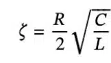
Consider the earlier equation: 

where,

By rewriting ζ in terms of α and ω, you have: 

The damping ratio was 2.0 when values were set to C = 2.0µF, L = 5.0mH and R = 200Ω. By changing C to 1.0µF, the damping ratio is approximately 1.41. Since this is still considered an overdamped condition, you can use the equation for an overdamped case to compare 2.0µF and 1.0µF of capacitance, Figure 6. 

Figure 6: Current over time for an overdamped circuit with different capacitor values in an RLC circuit

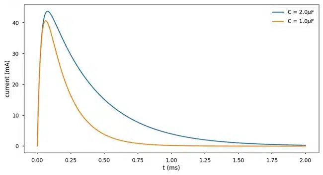
The area under 1.0µF capacitance case is smaller, which is reasonable to expect from a smaller capacitor that stores less charge. 

Here, we’ve explored:  

  • The three relevant equations for current waveform in an RLC circuit
  • The cases in which those equations are valid (depending on the damping ratio range) 
  • How adjusting the capacitance value in the RLC circuit changes the shape of the waveform

Related

Source: Knowles Precision Devices

Recent Posts

Vishay Extends Aluminum Capacitors Rating Up to 600 V for DC Links

15.1.2026
16

Würth Elektronik Introduces Product Navigator for Passive Components

14.1.2026
40

Panasonic Passive Components for Reliable Robotic Arms

14.1.2026
46

DC/DC Push‑Pull Converter vs PSFB Design Guide

12.1.2026
60

Rubycon PMLCAP DC‑Link Film Capacitors in Mass Production

9.1.2026
60

YAGEO High‑Capacitance X7R Automotive MLCC Extensions

8.1.2026
59

How Metal Prices Are Driving Passive Component Price Hikes

8.1.2026
294

Modelithics COMPLETE Library v25.8 for Keysight ADS

7.1.2026
39

Taiyo Yuden Releases 165C Automotive Multilayer Metal Power Inductor in 1608 Size

7.1.2026
38

Upcoming Events

Jan 21
18:00 - 18:45 CET

To Rogowski or not to Rogowski

Jan 27
16:00 - 17:00 CET

Simplifying Vehicle Development with Automotive Ethernet and Zonal Smart Switch Technologies

Feb 24
16:00 - 17:00 CET

Designing Qi2 Wireless Power Systems: Practical Development and EMC Optimization

View Calendar

Popular Posts

  • Buck Converter Design and Calculation

    0 shares
    Share 0 Tweet 0
  • Boost Converter Design and Calculation

    0 shares
    Share 0 Tweet 0
  • LLC Resonant Converter Design and Calculation

    0 shares
    Share 0 Tweet 0
  • Flyback Converter Design and Calculation

    0 shares
    Share 0 Tweet 0
  • Ripple Current and its Effects on the Performance of Capacitors

    3 shares
    Share 3 Tweet 0
  • MLCC and Ceramic Capacitors

    0 shares
    Share 0 Tweet 0
  • How Metal Prices Are Driving Passive Component Price Hikes

    0 shares
    Share 0 Tweet 0
  • Dual Active Bridge (DAB) Topology

    0 shares
    Share 0 Tweet 0
  • What is a Dielectric Constant and DF of Plastic Materials?

    4 shares
    Share 4 Tweet 0
  • Degradation of Capacitors and its Failure Mechanisms

    0 shares
    Share 0 Tweet 0

Newsletter Subscription


Passive Components Blog

© EPCI - Leading Passive Components Educational and Information Site

  • Home
  • Privacy Policy
  • EPCI Membership & Advertisement
  • About

No Result
View All Result
  • Home
  • Knowledge Blog
  • PCNS

© EPCI - Leading Passive Components Educational and Information Site

This website uses cookies. By continuing to use this website you are giving consent to cookies being used. Visit our Privacy and Cookie Policy.
Go to mobile version