


by Rudy Ramos, Technical Content Marketing at Mouser Electronics. Capacitors can provide vital ride-through (or hold-up) energy or mitigate ripple and noise in power-conversion circuits. Choosing the right type can profoundly affect a system’s overall size, cost, and performance.
With their low equivalent series resistance (ESR), which allows for good ripple-current handling as well as high surge-voltage ratings and self-healing properties, film capacitors are strong candidates for many power-conditioning duties in key applications like electric vehicles, renewable energy, and industrial drives. They’re especially suited to scenarios where no hold-up (or ride-through) is required, such as in the event of an outage or between line-frequency ripple peaks, and where there’s a need to source or sink large high-frequency ripple currents with high reliability and low losses.
Film capacitors are also an excellent fit in applications that operate high dc bus voltages to minimize ohmic losses. Because aluminum electrolytic capacitors are only available with ratings up to about 550 V, applications operating at higher voltages require multiple devices to be connected in series. It then becomes necessary to prevent voltage imbalance, either by selecting capacitors with matched values, which is expensive and time-consuming, or adding voltage-balancing resistors that impose additional energy losses and BOM cost.
On the other hand, aluminum electrolytic remain a strong choice when sheer energy storage density (joules/cm3) is the prime concern. One example is in commodity offline power supplies, where cost-effective bulk energy storage is needed to maintain the dc output voltage in the event of power outage, without battery backup. Suitable derating can mitigate the lifetime and reliability issues often associated with aluminum electrolytics.
However, it’s true that aluminum-electrolytic capacitors can only tolerate overvoltages of about 20% before damage occurs, whereas film capacitors can withstand exposure to voltages up to about double their rating for short periods. Self-healing ensures safer response to occasional stresses, as typically encountered in real-world applications.
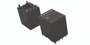
In addition, film capacitors can provide easier connection and mounting options, and are non-polarized and hence immune to reverse-connection errors. They’re often packaged in insulated, volumetrically efficient rectangular “box” enclosures. Various electrical connection types are available, such as screw terminals, lugs, “fastons,” or bus bars.
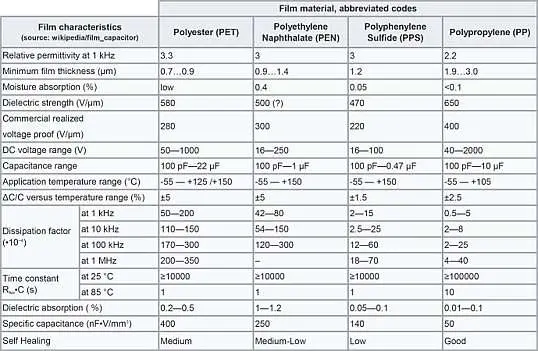
Table 1 compares properties of film-capacitor types in common use. Polyester types are utilized at low voltages, while polypropylene typically exhibits the lowest losses and highest reliability under stress thanks to its low dissipation factor (DF) and high dielectric breakdown per unit thickness. The DF is also relatively stable with temperature and frequency. Segmented high-crystalline metallized polypropylene is also available, and offers energy density comparable to that of aluminum electrolytics.
Choosing the Right Capacitor
Analyzing some common power-conversion circuits can show how capacitor technology selection profoundly influences size, weight, and cost, depending on whether capacitance is needed for energy storage or to handle ripple or noise.
For example, comparing electrolytic and film capacitors when used as bulk capacitance for a 1-kW offline converter starkly illustrates the differences between properties of the two types. The converter, as shown in Figure 1, features a power-factor-corrected front end and has nominal dc-bus voltage (Vn) of 400 V.
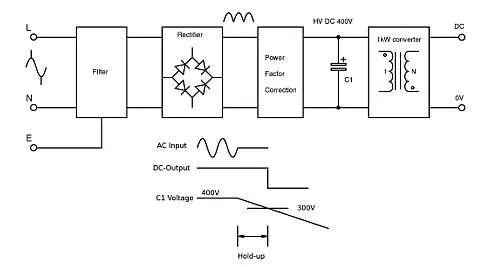
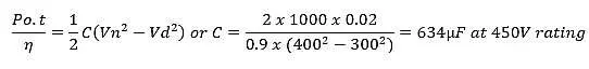
Let’s assume efficiency is 90% and dropout voltage (Vd) 300 V, below which output regulation is lost. If an outage occurs, the bulk capacitor C1 supplies energy to maintain constant output power as the bus voltage drops from 400 V toward 300 V. We can calculate the value of C1 needed to give 20-ms ride-through before the voltage falls below 300 V:
A 680-µF, 450-V aluminum-electrolytic capacitor from the TDK-EPCOS B43508 series, in a 35-mm-diameter × 55-mm case size, meets the requirement with overall volume of 53 cm3 (about three cubic inches). In contrast, a solution using film capacitors would be impractically large: Up to 15 TDK-EPCOS B32678 film capacitors may need to be connected in parallel, resulting in a total volume of 1500 cm3 (91 cubic inches).
The choice would change dramatically if the capacitor were needed only to control ripple voltage on a dc line, such as in an EV powertrain. The bus voltage could be 400 V, as before, but supplied by a battery, so there’s no ride-through requirement. It would be realistic to seek to limit the ripple within say 4 V rms, while a downstream converter draws 80-A rms pulse-current at a switching frequency of 20 kHz. The capacitance required is:
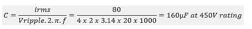
A 180-µF, 450-V electrolytic capacitor from the TDK-EPCOS B43508 series has a ripple-current rating of about 3.5 A rms at 60°C, including frequency correction. To handle 80 A would require 23 capacitors in parallel, giving unnecessary large capacitance of 4140 µF and a total volume of about 1200 cm3 (73 cubic inches). This concurs with the 20-mA/µF rule of thumb for electrolytic-capacitor ripple-current ratings.
Using film capacitors from the TDK-EPCOS B32678 series, just four devices in parallel give a 132-A rms ripple-current rating in a volume of 402 cm3 (24.5 cubic inches). Moreover, if the ambient temperature can be expected to remain below 70°C, capacitors in an even smaller case size can be chosen.
There are other reasons that make film capacitors a superior choice. The excessive capacitance of the parallel electrolytics could cause problems such as controlling the energy in inrush current. In addition, film types are far more robust in the event of transient overvoltages on the dc-link connection, which are common in light traction applications such as electric vehicles.
Similar analysis would be valid for applications such as UPS systems, power conditioning in wind or solar generators, general grid-tied inverters, and welders.
Film as First Choice
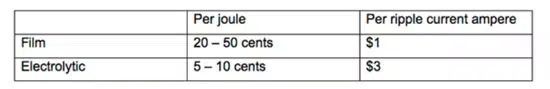
The relative costs of film or electrolytic capacitors can be analyzed from a bulk-storage or ripple-capability standpoint. Figures published in 2013 compare typical costs for a dc bus powered by a rectified 440-V ac supply (Table 2).
With this analysis in mind, film capacitors are an excellent choice for decoupling, switch snubbing, and filtering applications such as EMI suppression or inverter-output filtering.
A decoupling capacitor placed across the dc bus of an inverter or converter provides a low-inductance path for circulating high-frequency currents. A rule of thumb is to use about 1 µF per 100 A switched. It’s worth noting that connections to the capacitor should be kept as short as possible to avoid inducing transient voltages. When current is large and frequency is high, changes of 1000 A/µs are possible.
Considering that PCB traces can have inductance of about 1 nH/mm, each millimeter can be 1 V transient according to:
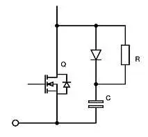
In a switch-snubbing circuit, the capacitor is placed in series with a resistor/diode combination and connected across the power switch—typically an IGBT or MOSFET—to control dV/dt (Fig. 2). The snubber slows ringing, controls EMI, and prevents spurious turn-on/turn-off. The snubber capacitance is typically chosen to be about twice the sum of the switch output capacitance and mounting capacitance. The resistance value is then chosen to critically damp any ringing.
EMI Suppression
Film capacitors are also ideal as X and Y capacitors to reduce differential-mode and common-mode noise, respectively (Fig. 3), leveraging their self-healing and transient-overvoltage capabilities. Safety-rated X1 (4kV) or X2 (2.5 kV) capacitors are connected across power lines, and are typically polypropylene types with capacitance value in the microfarads as needed to comply with applicable EMC standards.
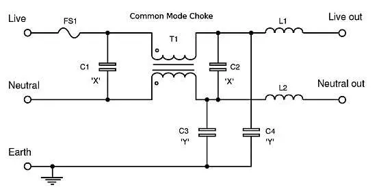
Y capacitors with low connection inductance are connected in line-to-earth positions. In Fig. 3, the Y1 or Y2 capacitors, rated for 8-kV and 5-kV transients, respectively, are connected in line-to-earth positions as shown. Leakage current considerations limit the amount of capacitance that can be applied. Although the low connection inductances of film capacitors help keep self-resonances high, external connections to the ground system should also be kept short.
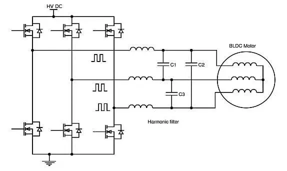
Inverter Output Filtering
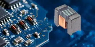
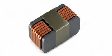
Non-polarized film capacitors combined with series inductors, often in a single module, create low-pass filters for attenuating high-frequency harmonics in the ac output of drives and inverters (Fig. 4). These are increasingly used for meeting system EMC requirements and reducing dV/dt-related stress on cabling and motors, particularly when the load is distant from the drive unit.
Conclusion
Knowing the relative strengths of electrolytic and film capacitors for power-conversion applications can help designers make the right choices for optimum overall size, weight, and bill-of-materials cost. They can be summarized as follows:
Electrolytic capacitors:
- Higher stored energy density (joules/cm3)
- Lower cost of bulk capacitance for “ride-through” of dc bus voltage
- Maintain ripple current rating at higher temperatures
Film capacitors:
- Lower ESR for superior ripple handling
- Higher surge-voltage ratings
- Self-healing boosts system reliability and lifetime