Passive Components Blog
No Result
View All Result
  • Home
  • NewsFilter
    • All
    • Aerospace & Defence
    • Antenna
    • Applications
    • Automotive
    • Capacitors
    • Circuit Protection Devices
    • electro-mechanical news
    • Filters
    • Fuses
    • Inductors
    • Industrial
    • Integrated Passives
    • inter-connect news
    • Market & Supply Chain
    • Market Insights
    • Medical
    • Modelling and Simulation
    • New Materials & Supply
    • New Technologies
    • Non-linear Passives
    • Oscillators
    • Passive Sensors News
    • Resistors
    • RF & Microwave
    • Telecommunication
    • Weekly Digest

    Modelithics Releases COMPLETE v26.1 for Keysight ADS

    April 2026 Interconnect, Passives and Electromechanical Components Market Insights

    SPICE Simulation of Non-Linear Resistors: Vishay’s Thermistor and PPTC Modelling Ecosystem

    KYOCERA AVX Introduces Traction‑Grade DC Link Film Capacitors

    When More Capacitance Hurts Reliability: The Role of the Metallic Skeleton in Tantalum Anodes

    Why Power Inductors Use a Ferrite Core With an Air Gap

    Wk 16 Electronics Supply Chain Digest

    YAGEO Introduces High‑Current Y2/X1 Film Capacitors for Wide-bandgap Power Systems

    Amphenol Explanded Liquid Cooling Connectors for AI, ESS and EV Systems

    Trending Tags

    • Ripple Current
    • RF
    • Leakage Current
    • Tantalum vs Ceramic
    • Snubber
    • Low ESR
    • Feedthrough
    • Derating
    • Dielectric Constant
    • New Products
    • Market Reports
  • VideoFilter
    • All
    • Antenna videos
    • Capacitor videos
    • Circuit Protection Video
    • Filter videos
    • Fuse videos
    • Inductor videos
    • Inter-Connect Video
    • Non-linear passives videos
    • Oscillator videos
    • Passive sensors videos
    • Resistor videos

    Why Power Inductors Use a Ferrite Core With an Air Gap

    Transformer-Based Power-Line Harvester Magnetic Design

    Thermal Modeling of Magnetics

    Standard vs Planar LLC transformers Comparison for Battery Chargers

    How Modern Tools Model Magnetic Components for Power Electronics

    Advanced Loss Modeling for Planar Magnetics in the Frenetic Planar Tool

    2026 Power Magnetics Design Trends: Flyback, DAB and Planar

    Enabling Software‑Defined Vehicle Architectures: Automotive Ethernet and Zonal Smart Power

    Calculating Resistance Value of a Flyback RC Snubber 

    Trending Tags

    • Capacitors explained
    • Inductors explained
    • Resistors explained
    • Filters explained
    • Application Video Guidelines
    • EMC
    • New Products
    • Ripple Current
    • Simulation
    • Tantalum vs Ceramic
  • Knowledge Blog
  • DossiersNew
  • Suppliers
    • Who is Who
  • PCNS
    • PCNS 2025
    • PCNS 2023
    • PCNS 2021
    • PCNS 2019
    • PCNS 2017
  • Events
No Result
View All Result
Passive Components Blog
No Result
View All Result

STMicro’s Newest Stepper Motor Driver: A 256-Microstep Driver with Integrated Control Logic Needs Precise Sense Resistors

24.4.2020
Reading Time: 4 mins read
A A

source: All about circuits article

STMicroelectronics offers their new microstepping motor driver that includes control logic and a power stage. Two precise sense resistors play an important role in the PWM current control—for both slow decay and mixed decay current recirculation conditions

RelatedPosts

Modelithics Releases COMPLETE v26.1 for Keysight ADS

April 2026 Interconnect, Passives and Electromechanical Components Market Insights

SPICE Simulation of Non-Linear Resistors: Vishay’s Thermistor and PPTC Modelling Ecosystem

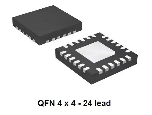
ST recently announced their new STSPIN820, which is an advanced microstepping motor driver that is capable of a stepping resolution of 1/256th of a step and integrates both the control logic and power stage in a small 24-pin QFN 4 × 4 mm package. Seems impressive.


Featured Figure 1. STSPIN820 microstepping motor driver. Image taken from the datasheet (PDF).


With a wide operating voltage range of 7 to 45 V, a host of protection features, and a low standby current of 45µA, this IC could be a good choice for applications such as 3D printers, sewing machines, and robotics.


A “Low” RDSon Value

This motor driver’s integrated power stage is advertised as having a low RDSon value (high side + low side) of 1Ω (typical). It seems to me, however, that 1Ω isn’t really all that low. In fact, in my dealings with motor drivers—granted my design experience in this regard is not exceedingly extensive—motor drivers with low RDSon values are in the range of hundreds of milliohms. So I would suggest that 1Ω might be better characterized as a typical RDSon value; if you disagree, let us know in the comments.


Figure 2. The STSPIN820’s “low”  RDSon values, from the datasheet (PDF).


External Sense Resistors

As noted in the datasheet, this IC requires two external sense resistors (RSNSA and RSNSB), and because these resistors play an important role in the PWM current control—for both slow decay and mixed decay current recirculation conditions—their values must be chosen carefully. Fortunately, ST has provided values for these resistors in a typical application (see image below), and they suggest values for other external passive components. They also offer a trick for easily achieving lower resistor values with higher power ratings; this trick—though it’s probably, hopefully, common knowledge for any electrical engineer—is simply placing multiple resistors in parallel. But hey, maybe ST thought that we might forget about this technique in this particular situation…so thanks, ST, for the reminder.


Figure 3. Recommended RSENSE resistor values and other recommended values for external components. Image taken from the datasheet (PDF).


Lately I’ve noticed datasheets that don’t offer much in the way of straightforward design guidance, so it’s good to see that ST has taken the time to provide this information.


A Set of Protection Features

The STSPIN820 comes with multiple protection features. Though not exactly uncommon among high-end (or even low-end) ICs these days, these features are nonetheless important additions to a reliable, user-friendly motor driver.

  • Short-circuit or overcurrent: Each power output node is protected against overload/overcurrent and short-circuit conditions, including short-to-ground, short-to-VS, and short-circuit between outputs. When an overcurrent condition occurs, the power stage is disabled and the Fault pin is driven low until the overcurrent condition is rectified (see image below).


Figure 4. Overcurrent and short-circuit protection management. Diagram taken from the datasheet (PDF).


  • Undervoltage lockout (UVLO): During power up, the power stage is disabled—and the Fault pin is forced low—until the voltage on the VS pin (actually, there are two VS pins and they must be at the same voltage) rises above the VS threshold voltage (VSth(ON)), which is 6.0 V (typical). The image below shows the undervoltage lockout protection scheme.


Figure 5. Undervoltage lockout (UVLO) protection management. Diagram taken from the datasheet (PDF).


  • Thermal shutdown: When the IC’s junction temperature reaches its threshold (TjSD = 160°C), the power stage is disabled and the Fault pin is driven low. Once the junction temperature retreats back to less than 120°C (which includes the thermal shutdown hysteresis value of 40°C), the fault condition is removed (see the image below).


Figure 6. Thermal shutdown protection management. Diagram taken from the datasheet (PDF).


The Microstepping Sequencer

For this device, ST uses three Mode inputs for achieving a stepping range from full-step to 1/256th of a step. As shown in the image below, each of the three mode settings (MODE1, MODE2, and MODE3) are clocked in on the rising edge of STCK (step clock input). And to allow for a very quick stepper motor response, the three mode settings can be changed at any time, and these changes are applied immediately.


Figure 7. Step mode configuration using the MODEx inputs, from the datasheet (PDF).

Related

Recent Posts

Modelithics Releases COMPLETE v26.1 for Keysight ADS

23.4.2026
9

April 2026 Interconnect, Passives and Electromechanical Components Market Insights

22.4.2026
34

KYOCERA AVX Introduces Traction‑Grade DC Link Film Capacitors

21.4.2026
37

YAGEO Introduces High‑Current Y2/X1 Film Capacitors for Wide-bandgap Power Systems

17.4.2026
29

Amphenol Explanded Liquid Cooling Connectors for AI, ESS and EV Systems

17.4.2026
15

Hirose Introduced BGA connector for PCIe Gen6 for AI and Edge Computing

17.4.2026
10

Samsung Introduces Ultra-High-Voltage 1500 V MLCCs for xEV Powertrains

16.4.2026
26

TDK Introduces High‑Voltage Common‑Mode Chokes for Compact 1250 V DC Converters

16.4.2026
28

Vishay Extends Power Inductors for DC/DC with 1212 Compact Case

16.4.2026
21

Upcoming Events

Apr 27
15:00 - 16:00 CEST

Commercial Space Screening Approach for Agile, High-Reliability Payloads

Apr 29
10:00 - 11:00 CDT

SEPIC Design Done Right

Apr 30
10:00 - 11:00 CDT

Programming Embedded Systems

View Calendar

Popular Posts

  • Buck Converter Design and Calculation

    0 shares
    Share 0 Tweet 0
  • Boost Converter Design and Calculation

    0 shares
    Share 0 Tweet 0
  • Flyback Converter Design and Calculation

    0 shares
    Share 0 Tweet 0
  • LLC Resonant Converter Design and Calculation

    0 shares
    Share 0 Tweet 0
  • MLCC and Ceramic Capacitors

    0 shares
    Share 0 Tweet 0
  • Dual Active Bridge (DAB) Topology

    0 shares
    Share 0 Tweet 0
  • Capacitor Charging and Discharging

    0 shares
    Share 0 Tweet 0
  • What Electronics Engineer Needs to Know About Passive Low Pass Filters

    0 shares
    Share 0 Tweet 0
  • Ripple Current and its Effects on the Performance of Capacitors

    3 shares
    Share 3 Tweet 0
  • MLCC Case Sizes Standards Explained

    0 shares
    Share 0 Tweet 0

Newsletter Subscription


Passive Components Blog

© EPCI - Leading Passive Components Educational and Information Site

  • Home
  • Privacy Policy
  • EPCI Membership & Advertisement
  • About

No Result
View All Result
  • Home
  • Knowledge Blog
  • PCNS

© EPCI - Leading Passive Components Educational and Information Site

This website uses cookies. By continuing to use this website you are giving consent to cookies being used. Visit our Privacy and Cookie Policy.
Go to mobile version