In conjunction with the increased use of GaN semiconductor, which can operate a high frequency, higher frequencies for switching power supplies have become feasible.
Ferrite materials are used in transformer products, but core loss (iron loss) varies greatly depending on the driving frequency, and they are key components in transformer design. This article presents information on the features of PC200 material, which was developed by using GaN, and key points concerning its use.
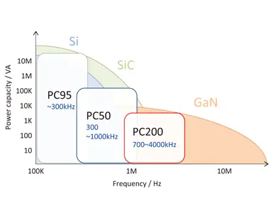
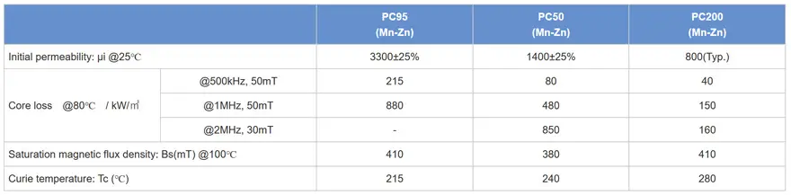
Characteristics and lineup of materials compatible with high frequency
TDK’s Mn-Zn ferrite cores compatible with high frequency support mass production of PC95 material. PC200 is a ferrite material with low loss at frequencies from 700kHz to 4MHz and maximum electric power conversion capacity at 1.8MHz to approximately 2MHz. For example, automotive ECUs are always equipped with a DC-DC converter to suppress battery voltage fluctuations, but the switching frequency has increased to frequencies that avoid the AM band (1.8MHz to 2.2MHz) for EMI countermeasures. PC200 is the most suitable material for transformers operated at these high frequencies.
Expected effects of using PC200 in products
- Support for compact transformers in conjunction with higher frequencies
- Temperature increase control effects under high-frequency operating conditions
Main applications
- Consumer devices: High-efficiency, compact adapters, switching power supplies, etc.
- Industrial equipment: DC-DC converters, high-output compact switching power supplies, inverters, etc.
- Automotive components (EVs, HEVs): Onboard chargers, DC-DC converters, etc.
| Material Name | Frequency Range*1 (kHz) | Product Status | Samples |
|---|---|---|---|
| PC95 | -300 | Mass production | Available |
| PC50 | 300 – 1000 | Mass production | Inquire |
| PC200 | 700 – 4000 | Advance preparations | Available (Inquire*2) |
*1 Frequency ranges are approximate. Verification of operation with actual devices is necessary.
*2 Please inquire regarding available sizes and quantities of PC200.
Superiority over earlier ferrite materials when operating at high frequency
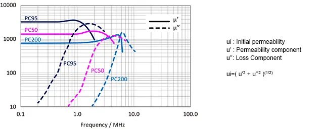
Representative values when intersection is not specified
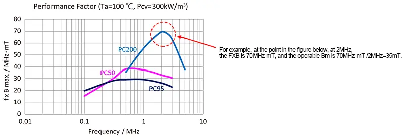
Performance Factor (f×B)
Magnetic flux densities ΔB that can be used at operating frequencies can be calculated from the Performance Factor (f×B) graph.
The operating magnetic flux density is related to core loss (core heat generation).
The operating magnetic flux density is calculated by the following
formula, but the value limited by either the saturation magnetic flux
density or the core loss is the design value.
Magnetic flux density: B; Operating voltage: E; Number of windings: N; Core cross section area: A; Switch on time: T

A flyback or forward converter that operates at 300KHz or less is limited by the core loss for circuits that use B in the first and third quadrants such as saturated magnetic flus, LLC resonance, and full bridge.
When operating at 200KHz or higher in particular, set the operating magnetic flux density by making reference to the fXB curve on the right.
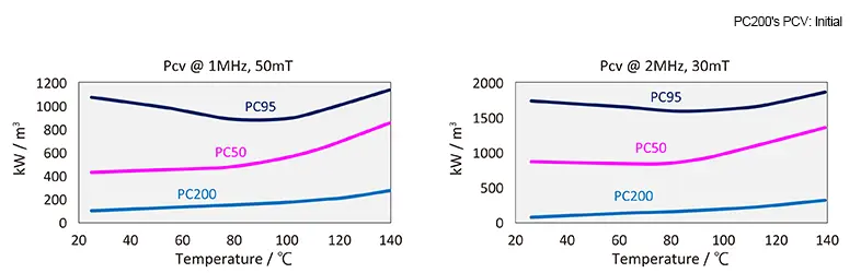
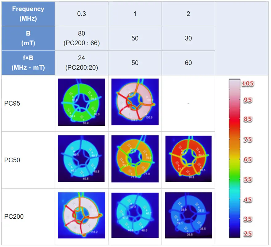
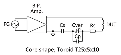
Core temperature reference test
The ferrite core of PC200 material can suppress heat generation when operating at high frequency. The optimal operating frequency changes according to the material.
Warnings concerning the use of PC200 material
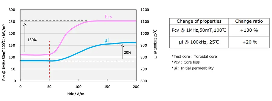
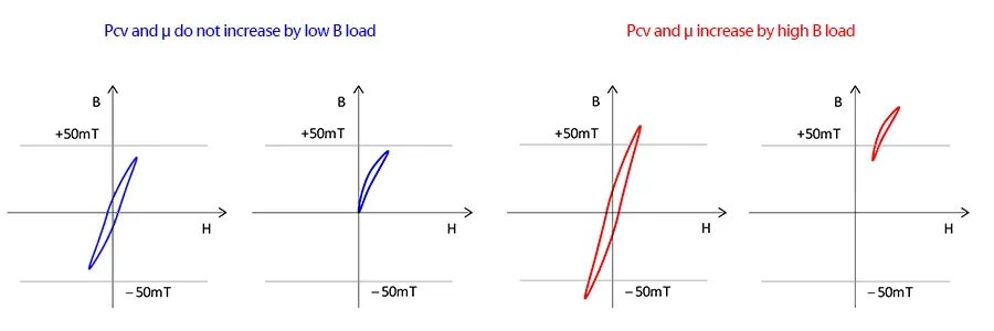
Shown in Figure 6, when PC200 material is operated with high magnetic flux, μi increases by 20% and core loss increases by 130%. When designing products using PC200 material, it is recommended that it be used with Hdc = 50 (A/m) or less. Figured 7 shows an example where Hdc exceeded 50 (A/m).
- When operating in the first and third quadrants, Hdc exceeds 50 on one side.
- Hdc exceeds 50 when direct current is imposed.