Passive Components Blog
No Result
View All Result
  • Home
  • NewsFilter
    • All
    • Aerospace & Defence
    • Antenna
    • Applications
    • Automotive
    • Capacitors
    • Circuit Protection Devices
    • electro-mechanical news
    • Filters
    • Fuses
    • Inductors
    • Industrial
    • Integrated Passives
    • inter-connect news
    • Market & Supply Chain
    • Market Insights
    • Medical
    • Modelling and Simulation
    • New Materials & Supply
    • New Technologies
    • Non-linear Passives
    • Oscillators
    • Passive Sensors News
    • Resistors
    • RF & Microwave
    • Telecommunication
    • Weekly Digest

    Modelithics Library for MATLAB: Measurement-Based Models for Microwave and RF Passive Components

    Bourns Extends Multilayer Chip Inductors Offer for RF and Wireless Designs

    Researchers developed a polymer capacitor by combining two cheap, commercially available plastics. The new polymer capacitor makes use of the transparent material — pictured here, with vintage Penn State athletic marks visible through it — to store four times the energy and withstand significantly more heat.  Credit: Penn State

    Penn State Demonstrated Polymer Alloy Capacitor Film with 4× Energy Density up to 250C

    ECIA January 2026 Reports Strong Sales Confidence

    Vishay Unveils Ultra-Compact 0201 Thick Film Chip Resistors

    Würth Elektronik Component Data Live in Accuris

    Coilcraft Releases Automotive Common Mode Chokes

    MLCC Manufacturers Consider Price Increase as AI Demand Outpaces Supply

    YAGEO Extends Antenna Portfolio with Wi‑Fi 6E/7 and Tri‑band GNSS Solutions

    Trending Tags

    • Ripple Current
    • RF
    • Leakage Current
    • Tantalum vs Ceramic
    • Snubber
    • Low ESR
    • Feedthrough
    • Derating
    • Dielectric Constant
    • New Products
    • Market Reports
  • VideoFilter
    • All
    • Antenna videos
    • Capacitor videos
    • Circuit Protection Video
    • Filter videos
    • Fuse videos
    • Inductor videos
    • Inter-Connect Video
    • Non-linear passives videos
    • Oscillator videos
    • Passive sensors videos
    • Resistor videos

    2026 Power Magnetics Design Trends: Flyback, DAB and Planar

    Enabling Software‑Defined Vehicle Architectures: Automotive Ethernet and Zonal Smart Power

    Calculating Resistance Value of a Flyback RC Snubber 

    One‑Pulse Characterization of Nonlinear Power Inductors

    Thermistor Linearization Challenges

    Coaxial Connectors and How to Connect with PCB

    PCB Manufacturing, Test Methods, Quality and Reliability

    Transformer Behavior – Current Transfer and Hidden Feedback

    Choosing the Right Capacitor: The Importance of Accurate Measurements

    Trending Tags

    • Capacitors explained
    • Inductors explained
    • Resistors explained
    • Filters explained
    • Application Video Guidelines
    • EMC
    • New Products
    • Ripple Current
    • Simulation
    • Tantalum vs Ceramic
  • Knowledge Blog
  • DossiersNew
  • Suppliers
    • Who is Who
  • PCNS
    • PCNS 2025
    • PCNS 2023
    • PCNS 2021
    • PCNS 2019
    • PCNS 2017
  • Events
No Result
View All Result
Passive Components Blog
No Result
View All Result

TDK Wireless Power Patterned Coil Explained

22.8.2022
Reading Time: 7 mins read
A A

TDK, a world leader in material technologies, manufacturing and electronic components, has recently developed and released a state-of-the-art, Qi compliant planar wireless power coil utilizing a unique copper patterning technology that provides multiple end-user benefits.

The Wireless Power Consortium [WPC] has designated this new coil as MP-A28, while the corresponding TDK part number is WCT38466-N0E0SST01. TDK’s “pattern coil” technology allows for intricate coil patterns that cannot be duplicated by the use of discrete wires and yields tight trace width and gap control normally associated with the finest etching processes and technologies.

RelatedPosts

TDK Releases High Temp 175C Automotive NTC thermistors

TDK Unveils 125C Compact DC Link Film Capacitors

TDK Releases Stackable µPOL 25A Power Modules

Also unique to TDK’s technology, is the ease and flexibility to accurately change the copper trace thickness, depending on the application requirements, which is not available by traditional copper coil techniques.

Background

TDK has a long history of utilizing copper plating processes to construct metal coil structures used within power inductors and has now leveraged this proven mature technology and applied it to wireless power coils. TDK’s TFM power inductor series has used a similar high aspect plating (HAP) copper technology to increase the coil pattern’s cross-sectional area to reduce direct current resistance (DCR). From this vast experience, the patterning and plating processes have been improved to the point where they can now be used in wireless power transmit (Tx) coils that traditionally are required to use litz wire.

The Qi approved MP-A28 coil consists of 3 key innovative areas:

  • 1) a revolutionary and patented coil pattern design
  • 2) an additive copper plating process applied on a carrier PET film and
  • 3) a “wet process” high permeability, high magnetic flux density saturation (Bs) value magnetic shield upon which the coil structure is attached.

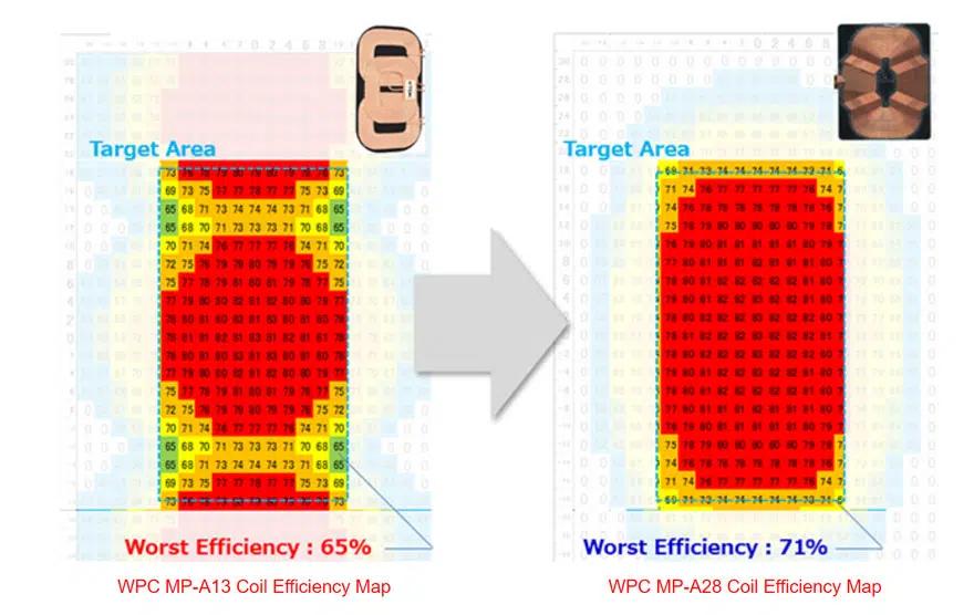
The flexible coil patterning capability allows for better control and shaping of the magnetic field (H), thus concentrating the magnetic flux (ɸ) where it optimizes magnetic coupling with the Rx device and efficiency. The patterning allows for the charging efficiency “peaks” and “valleys”, typical of multiple coil structures, to be reduced. The patterning also reduces/removes the low efficiency (“dead”) areas around the edges of the complete coil.

The coil plating process is as an additive process where copper is plated on a designated location. This differs from printed circuit boards (PCBs) and/or flex printed boards (FPCs) where a solid copper sheet is etched and only leaves the desired copper pattern as a subtractive process.

The shield “wet process” uses Mn-Zn ferrite material and is applied as a wet “slurry” to a carrier film to a thickness of 0.3 mm … though it can be as thin as 0.1 mm. After being applied to the film the ferrite is then sintered and pre-cracked.

For the dominant low power wireless charging standard by the Wireless Power Consortium, most of the approved standard transmit (Tx) coils have historically been wire wound based. More specifically, litz wire has been used. This multi-strand wire type, with its greater copper surface area, is used to reduce skin effect losses which contribute to higher alternating current resistance (ACR) at the operating frequency. Because of this phenomenon, the MP-A28’s pattern coil also utilizes a patented multi-layer stacking structure to help mitigate AC copper losses.

MP-A28 Pattern Coil Features and Benefits

Figure 1: Thickness Comparison of Wireless Coil WPC 15W Tx Tri-Coil of wire-wound type.

TDK’s new pattern coil technology implements various new material processes and construction techniques to achieve a wide spectrum of features and benefits to the end-user. Some of the key benefits being:

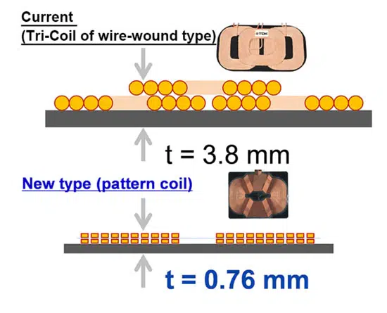
Thin – the tightly controlled copper plating thickness, available from 5 um to 150 um, along with a wet process 0.3 mm Mn-Zn ferrite shield, allow for a total coil assembly thickness of 0.76 mm for MP-A28 15W Qi compliant transmit coils. This results in thinner and lighter over all charger designs utilizing the MP-A28 coil assembly.

Having a thin copper coil pattern also has a system performance benefit. Magnetic coupling (K) is impacted by the physical distance between the transmit (Tx) and receive (Rx) magnetic shields. With the ultra-thin coil pattern, this results in the MP-A28 coil shield being closer to the charge surface, closer to the Rx device and thus improving magnetic coupling and efficiency.

Weight reduction – especially now as electric vehicle makers try to extend their battery charge and vehicle range, weight reduction continues to be a major talking point. With TDK’s MP-A28 coil, the thinness capability of the wet process/higher permeability (µ’) material, allows for a Tx coil weight reduction while still maintaining the required charging performance.

Electrical parameter consistency – The MP-A28 coil uses a photo mask/electroplating process, which yields air coils with less than 0.5% electrical variation. The MP-A28 coil also uses a co-planar structure for both the copper coil patterning and the ferrite shield. All of these ensure that the complete coil’s inductance (Ls) and resistance (Rs) values do not vary as they do with wire wound coils. Wire wound coils have insulation thickness variation, turn to turn winding variations in terms of co-planarity, and wire tautness control issues on the wire during winding which changes the magnetic length and respective Ls value.

Intricate coil patterning designs – TDK’s highly precise copper additive process creates opportunities to design irregular shaped coil patterns that help reduce “dead zones” where the charging efficiencies are diminished or completely not working as with traditional wire wound coils. The innovative MP-A28 coil pattern also allows the magnetic field (H) to be shaped and the magnetic flux (ɸ) to be focused in the regions of best charging. This also helps keep the magnetic field away from any neighboring metal objects and limits the magnetic flux getting into other areas of the charging device [phone].

Figure 2: Comparison of Wireless Coil Magnetic Flux Distribution.

With the more uniform magnetic field, an improvement in efficiency is also achieved in the event of misalignment between the Tx coil and the Rx coil within the to-be-charged device.

Figure 3: Comparison of Wireless Coil Efficiency.

Additionally, the new MP-A28 coil consists of multiple traces in parallel on multiple layers to increase each effective turn’s surface area to minimize copper trace alternating current (AC) skin effects that increase the AC resistance (ACR) which subsequently increases wire losses and temperature rise and therefore, reduce efficiency.

Reduced part count – the Qi complaint MP-A28 is designed as a single charge coil structure that is sized and shaped to provide better coverage than tri-coil configurations. Since there is only a single coil, many of the duplicate electronic parts associated with the tri-coil’s structure can be eliminated and thus reducing part count and BOM costs. The MP-A28 requires only one driver, one switch and one resonant capacitor bank (Cs) and may also eliminate thermistors, if used.

R+202:218obust automotive design – automotive applications have stringent requirements not imposed on other applications and end markets. The pre-cracking process of the thin ferrite shield ensures that no additional cracking, and thus loss of performance, can occur in the event of unwanted events such as: mechanical shock, vibration, impacts, thermal shock, etc.

Ease of lead termination – due to the MP-A28 coil’s flat trace that is created by the patterning process, the coil is available with either copper leads or it can be supplied with connector/header pins to provide easy assembly when connecting to the main PCB containing the charging circuit’s components. TDK attaches these pins using a non-solder ultra-sonic welding process. This eliminates the need for thru-holes, soldering, de-soldering during rework, etc., as required when using wire wound coils.

Integrated NFC antennas – A major advantage of copper plating on a carrier film is that additional independent coil patterns can also be integrated on the same carrier layer. One common additional coil used in wireless charging transmit devices are near field communication (NFC) antennas. Since electro-plating is independent of the amount of patterning required, adding the NFC coil to the existing wireless power coil structure comes at a minimal cost. The NFC antenna then uses the existing ferrite shield … eliminating the need for dual shields and the corresponding cost. This reduces the required area needed to implement both technologies, as they are usually placed side by side, as well as reducing weight.

Optional EMI screen – The MP-A28 also has an optional EMI metal mesh screen that is a separate 30 um thick layer. This screen is intended to help meet the automotive CISPR 25 requirements. By placing the screen over the MP-A28’s coil pattern and then electrically grounding it, an effective and light weight EMI noise suppression solution can be obtained. The impact of adding the EMI screen to the stack-up is less than a 1% efficiency decrease.

Related

Source: TDK

Recent Posts

Bourns Extends Multilayer Chip Inductors Offer for RF and Wireless Designs

20.2.2026
7

Würth Elektronik Component Data Live in Accuris

19.2.2026
14

Coilcraft Releases Automotive Common Mode Chokes

19.2.2026
10

2026 Power Magnetics Design Trends: Flyback, DAB and Planar

13.2.2026
46

Vishay Releases Compact 0806 Low‑DCR Power Inductor

5.2.2026
34

Murata Publishes Power Delivery Guide for AI Servers

4.2.2026
126

Selecting Current Sense Transformers with Würth Elektronik REDEXPERT

3.2.2026
36

Enabling Software‑Defined Vehicle Architectures: Automotive Ethernet and Zonal Smart Power

2.2.2026
43

Calculating Resistance Value of a Flyback RC Snubber 

2.2.2026
59

Upcoming Events

Feb 24
16:00 - 17:00 CET

Mastering Galvanic Isolation: Ensuring Safety in Power Electronics

Mar 3
16:00 - 17:00 CET

Cybersecurity at the Eleventh Hour – from RED to CRA – Information and Discussion

Mar 21
All day

PSMA Capacitor Workshop 2026

View Calendar

Popular Posts

  • Buck Converter Design and Calculation

    0 shares
    Share 0 Tweet 0
  • Boost Converter Design and Calculation

    0 shares
    Share 0 Tweet 0
  • LLC Resonant Converter Design and Calculation

    0 shares
    Share 0 Tweet 0
  • Flyback Converter Design and Calculation

    0 shares
    Share 0 Tweet 0
  • Ripple Current and its Effects on the Performance of Capacitors

    3 shares
    Share 3 Tweet 0
  • Dual Active Bridge (DAB) Topology

    0 shares
    Share 0 Tweet 0
  • What is a Dielectric Constant and DF of Plastic Materials?

    4 shares
    Share 4 Tweet 0
  • MLCC and Ceramic Capacitors

    0 shares
    Share 0 Tweet 0
  • 3-Phase EMI Filter Design, Simulation, Calculation and Test

    0 shares
    Share 0 Tweet 0
  • MLCC Case Sizes Standards Explained

    0 shares
    Share 0 Tweet 0

Newsletter Subscription


Passive Components Blog

© EPCI - Leading Passive Components Educational and Information Site

  • Home
  • Privacy Policy
  • EPCI Membership & Advertisement
  • About

No Result
View All Result
  • Home
  • Knowledge Blog
  • PCNS

© EPCI - Leading Passive Components Educational and Information Site

This website uses cookies. By continuing to use this website you are giving consent to cookies being used. Visit our Privacy and Cookie Policy.
Go to mobile version