The article explains basic definition of inductance, impedance and inductive losses.
Inductors are not just abstract symbols in schematics but real magnetic components whose behavior depends on geometry, core material and operating point.
Building on the definitions discussed by Prof. Sam Ben‑Yaakov in his lecture on inductance and so‑called “AC” and “DC” inductors, this article connects the textbook parameters inductance, impedance, Q factor and DCR to the way real inductors store energy, saturate and dissipate losses in practical power‑electronics design. For a more in‑depth conceptual treatment of inductance types and energy‑centric thinking, see also the companion article “Inductance, AC Inductors and DC Inductors Explained in Video”
Key Takeaways
- The article covers the basics of Inductance Impedance and Inductor Losses, explaining key concepts and their practical implications.
- Different types of inductors, such as air coils and SMD inductors, affect their performance and efficiency in power electronics.
- Inductance (L), impedance (Z), quality factor (Q), and DC resistance (DCR) directly influence energy storage and loss mechanisms.
- Designers need to account for temperature effects, saturation current, and operational limits while selecting inductors.
- The article emphasizes an energy-centric view over traditional classifications of inductors, focusing on actual performance needs.
Inductance L
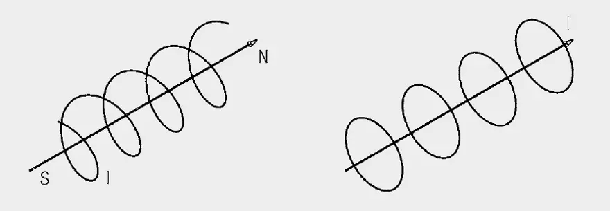
Not only magnetic materials possess a magnetic field, every current carrying conductor creates a magnetic field itself.
Energy can be temporarily stored in the magnetic field. This effect is technically exploited in coils, consisting of one or more wire windings. The synonymous term “inductor” has become established.
There are various types of inductors or coils:
- Air coils (without ferrite material)
- Choke coils with iron powder core or ferrite core
- Toroidal core coil
- Rod core coil
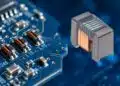
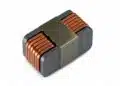
- SMD types are becoming increasingly important as a result of their small size. Besides wound SMD inductors, multiplayer inductors are becoming increasingly established.
All coils share a special behavior described in more detail by the following definitions.
Definition of Inductance L
A circuit element which responds to a current change with a counter-voltage, shows inductive properties. An inductor is a passive component, which, as an AC resistance, produces a counter-voltage, the self-induction voltage.
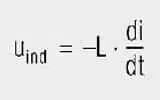
The self-induction voltage (Uind) at the terminals of the inductor is dependent on the rate of current change (di/dt) and a constant of proportionality, the inductance (L):
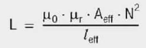
The inductance (L) of the coil is dependent on the core material, the geometry of the core material, the winding turns and the type of windings. The following equation applies generally for calculating an inductance (L):
The unit of inductance (L) is the Henry (H) = Vs/A
The inductance of cores with an inserted air gap can be calculated on the basis of the following formula:

lmean = mean magnetic path length in the core (without air gap)
lgap = path length of the air gap(s)
μr = relative permeability
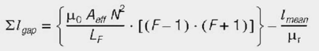
This formula inserted in formula for general inductance calculation produces:

This also allows an air gap width to be determined if the required inductance L and the other parameters are known. Here it must be borne in mind that the above formula only applies if μr is large and the air gap length is much smaller than the mean length in the core.
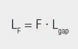
In order to include stray effects and their effect on inductance, McLyman proposes the following form of calculation for stray effects F:

wh = height of the winding
lgap = path length of the air gap(s)
Agap = cross-sectional area of the air gap
F = stray factor
The result is that the inductance LF changes by the calculated value Lgap times the stray factor F:
The positive influence of the air gap is an increased saturation current for the same core size. A disadvantage is that to attain a given L value, the number of turns now has to be raised and so, if no winding space is available, for thicker or more than one wire in a bifilar of trifilar winding, the DC resistance of the winding also increases.
Under no circumstances should the number of turns be reduced to compensate the stray effect – this additionally increases the induction and can lead to premature saturation.
The required air gap width for a given inductance L, taking into consideration the stray factor F, can be calculated to a first approximation as follows:
Typical inductance range of various inductor designs – see Table 1.
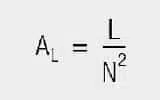
Definition of the AL value
To save the user from calculating the effective magnetic length (leff) and area (Aeff), the corresponding AL value is given for toroidal cores and sleeves. This represents the effective inductance for one winding and must be multiplied by the square of the winding turns (N) to give the actual inductance (L) – see eq.[8].
The (AL) value is the inductance (L) assuming the winding turns N = 1. Thus, given the AL value, the required number of coil windings can be found without having to take the long route of considering the core’s geometric data. see eq. [9]
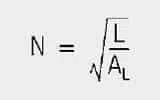
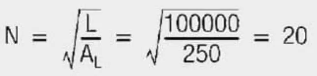
Example:
Required inductance 100 μH; the core has an AL value of 250 nH/N2
Result:
The core must have 20 windings to generate an inductance of 100 μH.
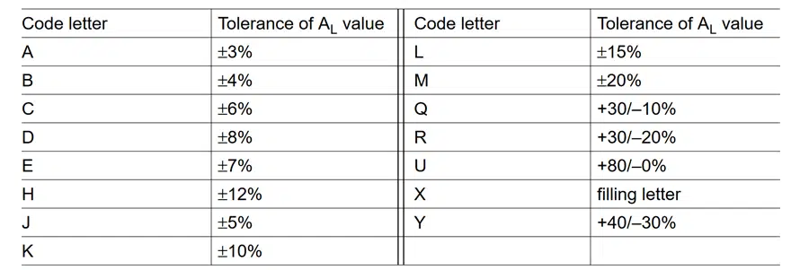
Tolerance code letters
The tolerances of the AL are coded by the letters in the third block of the ordering code in conformity with IEC 62358. The tolerance values available are given in the individual manufacturer’s data sheets and it is usually part of the ordering code.
Impedance Z
If an inductor is operated with AC voltage, it is clear that it represents a different resistance than in DC operation. The resistance for an AC voltage applied to the terminals of the coil is called impedance (Z).
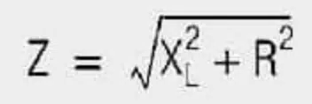
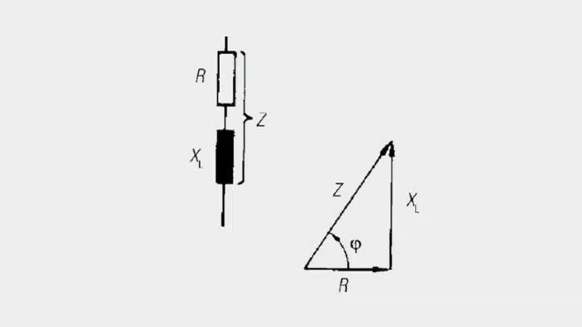
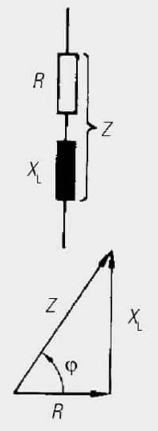
The impedance (Z) is frequency dependent and is composed of the geometric sum of the loss resistance (R) and the reactance (XL) of the ideal coil (L).
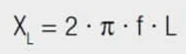
The reactance XL is defined as follows:
Inductance notions in nonlinear cores (summary)
In nonlinear magnetic materials, it is often useful to distinguish between the following inductance notions:”
| Inductance type | Definition perspective | Typical use in design |
|---|---|---|
| Total inductance | evaluated at a given current | Conceptual analysis, approximate energy storage estimation |
| Differential inductance | around an operating point | Small‑signal AC behavior, datasheet L–I curves, SMPS design |
Observation:
Impedance rises with increased frequency. This linear relationship continues to infinitely high frequencies for an ideal coil.

However, as a consequence of the frequency dependence of permeability and the construction of the coil and parasitic capacitance, the applicability of coils at high frequencies is limited. The impedance declines rapidly from the self-resonant frequency; the inductive nature of the coil disappears.
Self-Resonant Frequency (SFR)
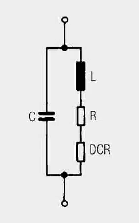
Every inductor also has capacitive coupling arising from its windings or multilayers. These parasitic capacities are symbolized by a capacitor (C) in the equivalent circuit. This condenser in the coil forms a parallel resonant circuit with the inductance.
At the self-resonant frequency, the input energy oscillates back and forth between the elements of inductance and capacitance. No more external energy is absorbed (ideal coil).
If a coil is operated above its resonance, it becomes ever more capacitive. In practice, coils should be operated well below their resonant frequency.
R Losses
No active power (heat loss) is dissipated in the reactance XL due to the 90° phase shift between voltage and current. The total coil losses can be combined into the loss resistance (R), which is connected in series with the ideal inductance (L). This results in the equivalent circuit of real inductance (see Figure 4.).
As the losses in R are however frequency dependent, the DC resistance (DCR) is also always defined in the data sheet specifications. This is dependent on the wire material used or the construction type of SMD inductors and is found at room temperature by a simple resistance measurement.
The size of the DC resistance DCR has a direct influence on the increase in temperature of the coil. Prolonged exceeding of the current rating should therefore be avoided. The total losses of the coil consist of both the losses in the DC resistance DCR and the following frequency dependent components:
- The losses in the core material (magnetic hysteresis loss, eddy-current loss)
- Additional losses in the conductor from the skin effect (current displacement at high frequencies)
- Magnetic field losses of the neighboring windings (proximity effect)
- Radiation losses
- Losses from additional magnetic shielding
All these loss components can be combined into a loss resistance (R). This loss resistance is primarily responsible for defining the quality of the inductor. Unfortunately, mathematical determination of the loss resistance R is not possible.
Therefore inductors are usually measured over the entire frequency range with an impedance analyzer. This measurement provides the individual components XL(f), R(f) and Z(f). The quality factor is defined as a quality characteristic of the inductor.
AC resistance and frequency‑dependent losses
The DC resistance (DCR) of an inductor is the winding resistance measured at or near 0 Hz and room temperature. It captures ohmic copper loss under pure DC conditions but does not account for frequency‑dependent effects such as skin effect, proximity effect and additional loss mechanisms in the winding and core.
For AC or pulsed currents, it is more meaningful to think in terms of an effective AC resistance which is the real part of the impedance seen at a given frequency. At low frequencies, tends to DCR, but at higher frequencies it can become several times larger due to non‑uniform current distribution in the conductors and increased core losses. Vector network analyzers or impedance analyzers can measure this directly, and many datasheets provide and or curves derived from such measurements.
When estimating losses in high‑frequency applications, designers should therefore base their calculations on at the relevant operating frequency, not on DCR alone. If only DCR is specified, the resulting loss estimate is optimistic and should be treated as a lower bound; for accurate thermal design, frequency‑dependent resistance from measurement or detailed manufacturer data is strongly recommended.
Copper Losses
The copper losses for inductive components are composed of direct current losses and eddy current losses. The direct current losses are calculated with Ohm’s law:
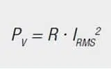
PV = power loss
R = DC resistance
IRMS = effective current
At higher frequencies there are also losses due to the skin effect and the proximity effect. These eddy current losses may be explained directly with Faraday’s law. The current flowing through a conductor generates a magnetic field around this conductor.
This magnetic field changes rapidly as a result of the high frequency, so that a voltage is induced in the conductor and in the neighbouring conductors. This voltage generates a current that opposes the original current. So additional currents are produced in the conductor, as well as in the neighbouring conductors.
Considering a single conductor, one speaks of the skin effect. For conductors through which high frequency currents flow, current only flows on the outer skin of the conductor (Figure 5.). The penetration depth at which the current density has fallen to a value of 1/e is given by:
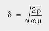
δ = penetration depth
ρ = resistivity
ω = angular frequency 2 πf
μ = permeability of the conductor (for copper μ0)
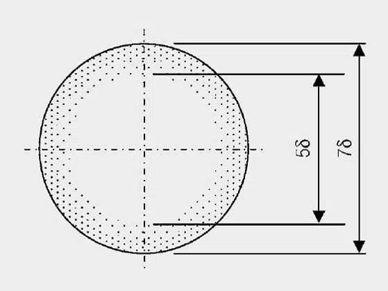
The penetration depth at 50 Hz is 9.38 mm, at 10 kHz it is 0.66 mm.
The proximity effect plays a far greater role for transformers, whereby neighbouring conductors generate fields displaced by current. A possibility for calculating eddy current losses for simple geometries is described by Dowell. The theory was further developed by Carsten. The mathematical description far exceeds the scope of this post.
It is far more important here to describe the options at hand to limit eddy current losses. Eddy current losses are dependent on the magnitude of the magnetic field. The way to limit eddy current losses is therefore to limit the magnetic field strength.
This can be achieved, for instance, by interleaving the windings, i.e. half of the primary winding is wound, then the secondary winding and thereafter the second half of the primary winding. This reduces the absolute value of the magnetic field and therefore also the eddy current losses. Figure 6. shows an illustration of the H field profile in a copper foil winding with a winding structure primary – secondary and half primary –secondary – half primary.
The magnetic field strength within a winding rises from the inside to the outside, because evermore turns (ever greater currents) are enclosed by field lines. The magnetic field of the secondary winding is opposite to the original field. This again serves to reduce the magnetic field. The reduction in the magnitude of the H field is plain to see.
Thin, flat conductors, e.g. copper foil, can also be used for winding. The thickness should be of the order of the penetration depth. This should only be used for small numbers of turns, because for higher numbers of windings, the large number of layers causes higher eddy current losses.
A further option for reducing eddy currents is to wind with thinner insulated wires rather than a thick wire. Here care must be taken that the single wires connected in parallel have the same current distribution. HF litz wires offer an option here, whereby single wires are twisted with one another so that on average every wire has the same position in the magnetic field. Care must also be taken with this option that the number of layers is not too great.
Definition of Quality Factor Q
The component of externally input energy converted into heat in the loss resistance R does not contribute towards the energy stored in the magnetic field. The larger these losses are, the poorer the inductor acts as a buffer.
This defines quality as the quality factor Q as follows:

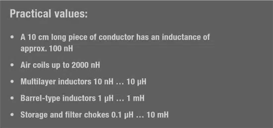
Practical values:
- Air coil Q up to 400
- Ferrite choke Q up to 150
- SMD multiplayer inductors Q up to 60
The quality-frequency graph on Figure 7. helps select the best inductor construction for the particular application.
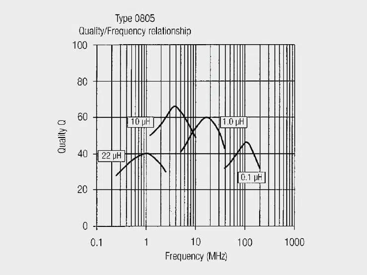
Observations:
- The quality rises to a peak value and then declines.
- Constant small losses in resistance R of the inductor can be assumed up to the peak quality value.
- Beyond the peak value, significant losses become evident, and the inductance also varies on account of non-linearity of the ferrite material.
- The operating range with the smallest losses can be defined up to the quality turning point. If the inductor is used at higher frequencies, the losses increase rapidly.
Temperature Behaviour
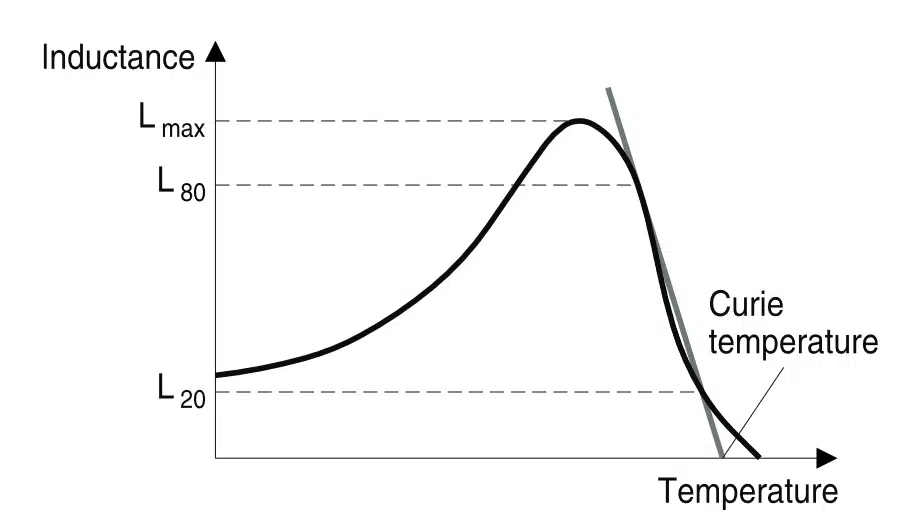
The initial permeability μi as a function of T is given for all materials. Important parameters for a μ(T) curve are the position of the secondary permeability maximum (SPM) and the Curie temperature. Minimum losses occur at the SPM temperature.
Above the Curie temperature TC ferrite materials lose their ferrimagnetic properties, i.e. μi drops to μi = 1. This means that the parallel alignment of the elementary magnets (spontaneous magnetization) is destroyed by increasing thermal activation.
This phenomenon is reversible, i.e. when the temperature is reduced below TC again, the ferrimagnetic properties are restored. The Curie tempertature TC is defined as the cross of the straight line between 80% and 20% of Lmax with the temperature axes (Figure 8).
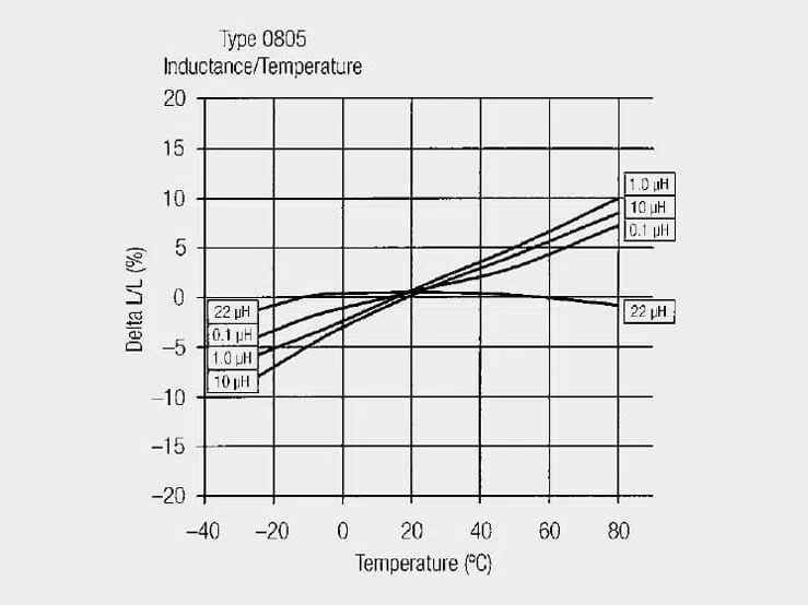
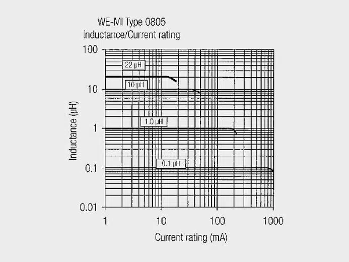
Coils having ferromagnetic core materials show a variable inductive behavior with the ambient temperature. If high demands are placed on the stability of filter circuits constructed with inductors (e.g. in measurement technology), it is expedient to select a coil with an almost linear temperature curve. The inductance change ΔL with respect to the inductance rating L of the coil is lowest in this case.
Figure 9. shows this graph for a 0805 multilayer inductor.
Rated Current
The rated current, which may be carried by an inductor, is defined more precisely by individual component types. The rated current is usually linked with a statement on the self-heating of the component. If the component is operated at its rated current it heats up above the ambient temperature by the temperature stated in the datasheet.
It must then be ascertained if the resulting temperature of the component is suitable for the application. Otherwise a component with a higher rated current loading capacity has to be selected. It has to be checked that by operating at the rated current the part does not exceed the operating temperature (otherwise derating is necessary).
Example:
The maximum current rating value of shielded multilayer inductor is attained if the increase in temperature of the component is greater than 20 °C for the selected test current.
Saturation Current
The saturation current of an inductor is the current at which the inductance value has dropped by a percentage specified in the datasheet.
Example:
Typical storage chokes saturation current specifies the current at which the inductance has dropped by 10%.
Note!
Especially for switching controller applications or applications with high capacitive loads or high inrush currents, the peak current flowing through the inductor can be significantly higher at the moment of switching-on than in regular operation. This may lead to total saturation of the component and therefore to potential consequential faults in the electronics. It is advisable to understand and to limit the current or to activate soft-start functions.
Inductance versus DC bias current
Real ferromagnetic cores have a nonlinear – characteristic, so permeability and thus inductance depend on the excitation level. As current increases, the core moves towards saturation, the incremental permeability drops and the effective inductance falls, even long before the formal saturation point is reached.
This leads to a distinction between total inductance, derived from the ratio at a given operating point, and differential (small‑signal) inductance, which is defined by the slope and describes the response to a small AC perturbation on top of a DC bias. In practice, the inductance versus DC current curves in datasheets almost always represent this differential inductance, measured by applying a DC bias and superimposing a small AC test signal.
For switch‑mode power supplies and other energy‑storage applications, it is this differential inductance at the intended operating current that matters most, rather than a nominal low‑current value at or near zero bias. When evaluating a part, designers should therefore read the inductance directly from the L–I curve at the maximum operating current (or ripple‑peak current) and ensure that it does not drop more than the allowable design margin (for example 20–30%) at that point.
Energy‑centric view: beyond “AC inductor” vs “DC inductor”
In many discussions, inductors are casually split into “DC inductors” that supposedly require an air gap and “AC inductors” that do not. From a physics and design point of view, this distinction is misleading. What really determines the size and core design of an inductor is the maximum magnetic energy it must store and the associated peak current, not whether the current has a DC component.
The stored energy is given by , so for a given inductance the energy scales with the square of the peak current. An inductor in a resonant AC tank with zero average current but large sinusoidal current can therefore require the same or even more stored energy than a DC choke with comparable RMS current, and will typically also benefit from a gapped core to avoid saturation and to keep inductance reasonably stable.
Seen this way, inductors with large DC bias and inductors with predominantly AC current are both energy‑storage components that should be designed and specified by peak current, flux density and allowable energy, rather than by verbal labels such as “AC” or “DC” inductor. The video‑based article “Inductance, AC Inductors and DC Inductors Explained in Video” walks through this energy‑centric view using examples from practical switch‑mode power‑supply magnetics.
Practical inductor selection checklist
The following checklist links the basic parameters discussed above to everyday inductor selection:
- Define the function of the inductor (energy storage in a switching converter, EMI filter, RF resonant tank, signal conditioning) and specify the required inductance value and tolerance.
- Determine the operating frequency range and ensure that the self‑resonant frequency is comfortably higher than the highest significant harmonic, so that the part behaves inductively in the intended band.
- Check quality factor Q versus frequency: aim for high Q in narrowband resonant circuits, but consider controlled or lower Q in broadband EMI filters or damping networks to avoid excessive peaking.
- Evaluate DCR and, where available, AC resistance at the operating frequency to confirm that copper and frequency‑dependent losses stay within allowed efficiency and temperature‑rise limits.
- Verify rated current, temperature rise current and saturation current against the worst‑case peak current in the application, using inductance‑versus‑current curves and applying appropriate design margin.
- Consider temperature effects on inductance and core losses over the expected ambient range, including superparamagnetic behavior and Curie temperature where relevant for ferrite materials.
- Review package, mounting and layout constraints and coordinate with purchasing so that inductance definition, test conditions (frequency and current) and current ratings are comparable across different suppliers.
Summary
Inductance, impedance, Q factor and DCR describe complementary aspects of real inductors that share the same physical origin in Faraday’s law and the magnetic properties of the core. Inductance and Q capture primarily the energy‑storage and reactive behavior, while DCR and AC resistance describe the resistive loss mechanisms that translate into heat and limit efficiency.
In nonlinear cores, there is no single unique inductance; instead, total and differential inductance must be interpreted at the relevant operating point, especially under DC bias in switch‑mode power supplies. Likewise, the traditional verbal separation between “AC inductors” and “DC inductors” is less important than the actual energy storage requirement, peak current and allowable flux density, which together determine whether a gapped core is needed and how large the magnetic component must be.
By combining parameter‑level understanding (L, Z, Q, DCR, SRF, temperature behavior) with an energy‑centric view and careful use of manufacturer curves, designers can select or design inductors that avoid saturation, meet loss and thermal limits and behave predictably across the intended frequency and operating‑point range.
Frequently Asked Questions about Inductance, Impedance and Inductor Losses
Inductance is the proportionality between the change of current and the induced voltage in a coil, determined by core material, geometry and number of turns. In real inductors it also depends on operating point, especially with magnetic cores, so inductance can change with current and temperature.
The impedance of an inductor is the combination of its reactance and loss resistance and increases with frequency in the inductive region. Around the self‑resonant frequency, parasitic capacitance causes the impedance to peak and then fall, and above this point the inductor behaves more like a capacitor.
DCR is the DC winding resistance measured at low frequency and room temperature and reflects pure ohmic copper losses. AC resistance includes frequency‑dependent effects such as skin effect, proximity effect and core‑related losses, and can be several times higher than DCR at high frequencies.
The quality factor Q expresses the ratio of reactive energy storage to resistive loss and is key for RF and resonant circuits. Self‑resonant frequency marks the transition from inductive to capacitive behaviour, so good designs keep the operating band comfortably below SRF to ensure predictable performance.
Magnetic cores have a nonlinear B–H curve, so effective permeability and inductance decrease as current pushes the core towards saturation. Datasheet L–I curves show this differential inductance versus DC bias, and designers use them to ensure inductance drop stays within an acceptable margin at peak current.
Rated current is limited by temperature rise in the winding, while saturation current is defined by a specified drop in inductance, often 10% or 20%. For reliable operation, the worst‑case peak current in the application should stay below both limits with safety margin, taking into account inrush and fault conditions.
Permeability, inductance and core losses vary with temperature and may pass through a secondary maximum or drop sharply near the Curie temperature. Designers must check the temperature dependence curves to ensure inductance remains within tolerance and losses stay acceptable across the full ambient range.
How to select an inductor for your circuit
- Define the function of the inductor
Start by clarifying whether the inductor is used for energy storage in a switching converter, EMI filtering, RF resonance or signal conditioning. From this, derive the required inductance value and tolerance and the acceptable size and cost range.
- Set the operating frequency range
Identify the fundamental frequency and dominant harmonics in your application. Select parts with a self‑resonant frequency significantly above this range so the inductor behaves inductively with stable reactance in the intended band.
- Check Q factor and impedance curves
Review the inductor’s Q versus frequency and impedance curves. For narrowband resonant or RF circuits, choose a part with a high Q peak in or above the operating band, while broadband EMI filters may benefit from moderate Q to avoid excessive peaking.
- Evaluate DCR and AC resistance
Use DCR to estimate copper loss at DC and low frequencies and, where available, use AC resistance data at the operating frequency for more accurate power‑loss calculations. Ensure total losses keep the component within its allowed temperature rise.
- Verify current ratings and L versus I
Compare the application’s worst‑case peak current, including inrush and transient conditions, with the rated current and saturation current in the datasheet. Use inductance‑versus‑current curves to confirm that inductance does not drop beyond your design margin at peak current.
- Consider temperature behaviour
Check inductance and permeability versus temperature and ensure performance is acceptable over the full ambient and self‑heating range. Pay attention to any secondary permeability maxima and to Curie temperature for ferrite cores used near their limits.
- Finalize package and sourcing constraints
Select a package and footprint compatible with your PCB layout, assembly process and insulation requirements. Align inductance definition, test frequency, test current and current ratings across potential suppliers to simplify qualification and second sourcing.