Passive Components Blog
No Result
View All Result
  • Home
  • NewsFilter
    • All
    • Aerospace & Defence
    • Antenna
    • Applications
    • Automotive
    • Capacitors
    • Circuit Protection Devices
    • electro-mechanical news
    • Filters
    • Fuses
    • Inductors
    • Industrial
    • Integrated Passives
    • inter-connect news
    • Market & Supply Chain
    • Market Insights
    • Medical
    • Modelling and Simulation
    • New Materials & Supply
    • New Technologies
    • Non-linear Passives
    • Oscillators
    • Passive Sensors News
    • Resistors
    • RF & Microwave
    • Telecommunication
    • Weekly Digest

    High Voltage MLCCs Meeting the Growing Demand for Efficiency in Power Conversion

    Bourns Releases High Power High Ripple Chokes

    KYOCERA AVX Releases Hermaphroditic WTW and WTB Connectors

    Radiation Tolerance of Tantalum and Ceramic Capacitors

    TDK Releases Compact Polypropylene Film Capacitors for Resonant Topologies

    Percolation Phenomenon and Reliability of Molded Power Inductors in DC/DC converters

    Root Causes and Effects of DC Bias and AC in Ceramic Capacitors

    Würth Elektronik Offers Accessory Humidity Sensor Filter Cap

    Knowles Unveils High-Performance Safety-Certified MLCC Capacitors

    Trending Tags

    • Ripple Current
    • RF
    • Leakage Current
    • Tantalum vs Ceramic
    • Snubber
    • Low ESR
    • Feedthrough
    • Derating
    • Dielectric Constant
    • New Products
    • Market Reports
  • VideoFilter
    • All
    • Antenna videos
    • Capacitor videos
    • Circuit Protection Video
    • Filter videos
    • Fuse videos
    • Inductor videos
    • Inter-Connect Video
    • Non-linear passives videos
    • Oscillator videos
    • Passive sensors videos
    • Resistor videos

    Percolation Phenomenon and Reliability of Molded Power Inductors in DC/DC converters

    Root Causes and Effects of DC Bias and AC in Ceramic Capacitors

    How to Calculate the Output Capacitor for a Switching Power Supply

    Switched Capacitor Converter Explained

    Understanding Inductor Dot Markings and Their Application in LTspice

    Accelerating Full Bridge LLC Resonant Converter Design with Frenetic AI

    Understanding Switched Capacitor Converters

    Coupled Inductors Circuit Model and Examples of its Applications

    Inductor Resonances and its Impact to EMI

    Trending Tags

    • Capacitors explained
    • Inductors explained
    • Resistors explained
    • Filters explained
    • Application Video Guidelines
    • EMC
    • New Products
    • Ripple Current
    • Simulation
    • Tantalum vs Ceramic
  • Knowledge Blog
  • Suppliers
    • Who is Who
  • Events
No Result
View All Result
Passive Components Blog
No Result
View All Result

The difference between inductive proximity, displacement, and eddy-current sensors

24.3.2016
Reading Time: 3 mins read
A A

source: EDN article, Patrick Mannion -March 23, 2016

It seems like engineering 101, but do you actually remember the specific differences between inductive proximity, inductive displacement, and eddy-current sensors? I asked a few friends and everyone had a pretty good idea, to varying degrees, but if you aren’t immersed in the topic the nomenclature can throw you off, as they’re all reliant on eddy currents.

RelatedPosts

High Voltage MLCCs Meeting the Growing Demand for Efficiency in Power Conversion

Bourns Releases High Power High Ripple Chokes

KYOCERA AVX Releases Hermaphroditic WTW and WTB Connectors

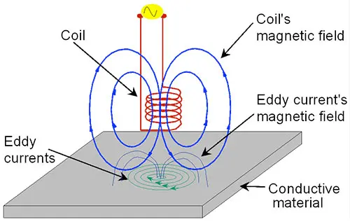
Eddy currents, also called Foucault current, are loops of electrical current induced within a conductor by a time-varying magnetic field in that conductor (Figure 1). This phenomenon of induction was first observed by Michael Faraday way back in 1831, and he summed up his experiments in Faraday’s Law. This of course states that the induced electrical current (electromotive force, or EMF) in a closed circuit is equal to the negative of the rate of change of the magnetic flux, or:

,

where \mathcal{E} is the EMF and ΦB is the magnetic flux.

Figure 1 Eddy currents are generated in a conductor by a time-varying magnetic field. When induced in a nearby conductor, the induced eddy currents oppose those of the originating magnetic field. (Image courtesy of Microwave Soft.)
Heinrich Lenz contributed by adding that the direction of the induced EMF always opposes the change that induced it.

These combined phenomena of induction, eddy current generation, and opposition are the fundamental principles of proximity, inductive displacement, and eddy-current sensors. The primary differences are structure and the accompanying electronics. So let’s start with the humble proximity sensor, the most basic embodiment and application of these principles.

The basic but well-loved proximity sensor is a binary device that simply tells whether or not a metallic object (the “target”) is present – or not. It comprises a wire coiled around a ferromagnetic core and an oscillator to generate an alternating current to create the time-varying magnetic field (Figure 2).

Figure 2 The basic proximity sensor is binary in that that it uses the opposing eddy currents induced in the target metal to detect absence or presence of the target. There’s no relative or absolute position information. (Image courtesy of robotpark.com.)
When a metallic target comes close, the opposing eddy currents induced in the target cause a drop in voltage across the originating oscillator. A detector circuit (Schmitt trigger) and amplifier (comparator) are used to switch the output, which can be normally closed (NC) or normally open (NO).

Inductive displacement sensors are a big step up from proximity sensors, but mostly thanks to more electronics and processing. Instead of a binary output, the classic inductive displacement sensors provide an analog output, typically via a 4-20-mA loop, that can be processed upstream to give a good idea of the target metal’s location relative to the sensor.

More advanced iterations of the inductive displacement sensor include linear variable differential transformers (LVDTs). These look similar to transformers except that the induced current in the secondary coils from the primary are dependent on the location of the target metal, which is usually a rod (Figure 3).

Figure 3 The linear variable differential transformer (LVDT) is a variety of the inductive displacement sensor that detects motion in a metal rod using the relative value of current induced in the secondary coils as the rod (core) travels back and forth (or up and down, as in a toilet float position-detection application).
Proximity and inductive displacement sensors suffice for the vast majority of applications requiring detection of metal targets in harsh environments where physical contact is not possible. For detection of non-metal targets in such environments, capacitive sensors can be used.

However, where ultimate precision and accuracy is required, that’s where eddy current sensors come in. These differ from proximity and inductive displacement sensors in that they use an air-core coil instead of a ferromagnetic core. This eliminates the magnetic losses and thermal nonlinearities associated with ferromagnetic cores, and it also gives eddy-current sensors much faster response times to resolve fast-moving targets, up to the MHz range. However, the trade-off is higher cost due to more precise manufacturing, production, and calibration to the target metal before shipping.

Note, that by dispensing with the ferromagnetic core, the magnetic field in an eddy-current (air core) sensor is not as focused, so the measurement distance, or air gap, needs to be narrower.

For accurate details on relative performance specifications, best to consult the datasheets of vendors such as Bosch, Omron, Baumer Group, Sensirion, Micro-Epsilon, and Pepprl+Fuchs.

Related

Recent Posts

Bourns Releases High Power High Ripple Chokes

8.8.2025
19

Percolation Phenomenon and Reliability of Molded Power Inductors in DC/DC converters

6.8.2025
29

Vishay Releases High Saturation 180C Automotive Inductors

6.8.2025
18

Additive Manufacturing of Mn-Zn Ferrite Planar Inductors

4.8.2025
17

PCNS 2025 Final Program Announced!

4.8.2025
78

TDK Announced Wide Frequency Automotive Wirewound POC Inductors

30.7.2025
35

Bourns Announced Shielded Power Inductor with High Saturation and Low Radiation

30.7.2025
23

Würth Elektronik Expands MagI³C with Variable Step-Down Modules

30.7.2025
24

Switched Capacitor Converter Explained

28.7.2025
47

TDK Presents Various Large-Size Ferrite Cores for Industrial Applications

25.7.2025
31

Upcoming Events

Sep 22
September 22 @ 13:00 - September 25 @ 15:15 EDT

Pre Cap Visual Inspection per Mil-Std-883 (TM 2017)

Sep 30
September 30 @ 12:00 - October 2 @ 14:00 EDT

MIL-Std-883 TM 2010

Oct 17
12:00 - 14:00 EDT

External Visual Inspection per MIL-STD-883 TM 2009

Oct 21
October 21 @ 12:00 - October 23 @ 14:15 EDT

Space and Military Standards for Hybrids and RF Microwave Modules

Nov 4
November 4 @ 12:00 - November 6 @ 14:15 EST

Wirebond Materials, Processes, Reliability and Testing

View Calendar

Popular Posts

  • Buck Converter Design and Calculation

    0 shares
    Share 0 Tweet 0
  • Boost Converter Design and Calculation

    0 shares
    Share 0 Tweet 0
  • Flyback Converter Design and Calculation

    0 shares
    Share 0 Tweet 0
  • LLC Resonant Converter Design and Calculation

    0 shares
    Share 0 Tweet 0
  • What is a Dielectric Constant and DF of Plastic Materials?

    4 shares
    Share 4 Tweet 0
  • Ripple Current and its Effects on the Performance of Capacitors

    3 shares
    Share 3 Tweet 0
  • Dual Active Bridge (DAB) Topology Explained

    0 shares
    Share 0 Tweet 0
  • How to Design an Inductor

    0 shares
    Share 0 Tweet 0
  • MLCC Case Sizes Standards Explained

    0 shares
    Share 0 Tweet 0
  • MLCC and Ceramic Capacitors

    0 shares
    Share 0 Tweet 0

Newsletter Subscription


Passive Components Blog

© EPCI - Leading Passive Components Educational and Information Site

  • Home
  • Privacy Policy
  • EPCI Membership & Advertisement
  • About

No Result
View All Result
  • Home
  • Knowledge Blog
  • Premium Suppliers

© EPCI - Leading Passive Components Educational and Information Site

This website uses cookies. By continuing to use this website you are giving consent to cookies being used. Visit our Privacy and Cookie Policy.
Go to mobile version