Passive Components Blog
No Result
View All Result
  • Home
  • NewsFilter
    • All
    • Aerospace & Defence
    • Antenna
    • Applications
    • Automotive
    • Capacitors
    • Circuit Protection Devices
    • electro-mechanical news
    • Filters
    • Fuses
    • Inductors
    • Industrial
    • Integrated Passives
    • inter-connect news
    • Market & Supply Chain
    • Market Insights
    • Medical
    • Modelling and Simulation
    • New Materials & Supply
    • New Technologies
    • Non-linear Passives
    • Oscillators
    • Passive Sensors News
    • Resistors
    • RF & Microwave
    • Telecommunication
    • Weekly Digest

    binder Releases Tool‑Tightenable M12 Connectors for Improved Reliability

    Vishay Introduced Thin Film Submount Platform for Optical and RF Modules

    Murata Introduces Crystal and NTC Set for Automotive UWB Timing

    Kyocera Developed Multilayer Ceramic Core Substrate for AI Packages

    Modeling Fringing Field Losses in Inductors & Transformers

    YMIN Introduces Polymer Tantalum Capacitors for AI Server SSDs

    Littelfuse Expands High-Voltage TVS Diodes

    DigiKey Adds 31k New In‑Stock Parts in Q1 2026

    Miniaturization of Tantalum Capacitors: Structural Limit Under Constant Rating

    Trending Tags

    • Ripple Current
    • RF
    • Leakage Current
    • Tantalum vs Ceramic
    • Snubber
    • Low ESR
    • Feedthrough
    • Derating
    • Dielectric Constant
    • New Products
    • Market Reports
  • VideoFilter
    • All
    • Antenna videos
    • Capacitor videos
    • Circuit Protection Video
    • Filter videos
    • Fuse videos
    • Inductor videos
    • Inter-Connect Video
    • Non-linear passives videos
    • Oscillator videos
    • Passive sensors videos
    • Resistor videos

    Modeling Fringing Field Losses in Inductors & Transformers

    Why Power Inductors Use a Ferrite Core With an Air Gap

    Transformer-Based Power-Line Harvester Magnetic Design

    Thermal Modeling of Magnetics

    Standard vs Planar LLC transformers Comparison for Battery Chargers

    How Modern Tools Model Magnetic Components for Power Electronics

    Advanced Loss Modeling for Planar Magnetics in the Frenetic Planar Tool

    2026 Power Magnetics Design Trends: Flyback, DAB and Planar

    Enabling Software‑Defined Vehicle Architectures: Automotive Ethernet and Zonal Smart Power

    Trending Tags

    • Capacitors explained
    • Inductors explained
    • Resistors explained
    • Filters explained
    • Application Video Guidelines
    • EMC
    • New Products
    • Ripple Current
    • Simulation
    • Tantalum vs Ceramic
  • Knowledge Blog
  • DossiersNew
  • Suppliers
    • Who is Who
  • PCNS
    • PCNS 2025
    • PCNS 2023
    • PCNS 2021
    • PCNS 2019
    • PCNS 2017
  • Events
No Result
View All Result
Passive Components Blog
No Result
View All Result

Thermoreflectance Thermal Imaging as thermal characterization technique for components

21.9.2018
Reading Time: 5 mins read
A A

Source: Alter Technologies article

Thermal image of components and its temperature map can be used for failure analyses, thermal process transients, or study of new materials. See more details in technical article published by Alter Technologies.

RelatedPosts

binder Releases Tool‑Tightenable M12 Connectors for Improved Reliability

Vishay Introduced Thin Film Submount Platform for Optical and RF Modules

Murata Introduces Crystal and NTC Set for Automotive UWB Timing

Temperature gradient in integrated circuits

Submicrometric-nanometric objects nowadays present in the design of integrated circuits induce singular heat transport phenomena leading to the formation of hot-spots or strong temperature gradients at specific local points, which compromises the suitable operation and reliability of microelectronic systems, and can potentially decrease the lifetime. The typical length of such singularities can reach the micro and submicronic scale. Hence temperature gradient over such systems has to characterized by advanced thermography instruments with high spatial resolution.

Why TTI?

Thermoreflectance Thermal Imaging (TTI) is a microscopy technique that provides temperature gradient contrast by analyzing the optical reflectance of the inspected surfaces. Amongst others TTI is employed to:

  • 2D thermal mapping.
  • Failure analyses and testing of microelectronic devices
  • The visualization of high-speed thermal transients
  • to study the implementation of innovative materials.

Main characteristics and advantages of the technique are:

  • Non-contact character.
  • High spatial resolution (micron and submicrometric), limited by the diffraction limit.
  • Temporal resolutions ~ 100µs.
  • Wide range temperature detection.

How it works?

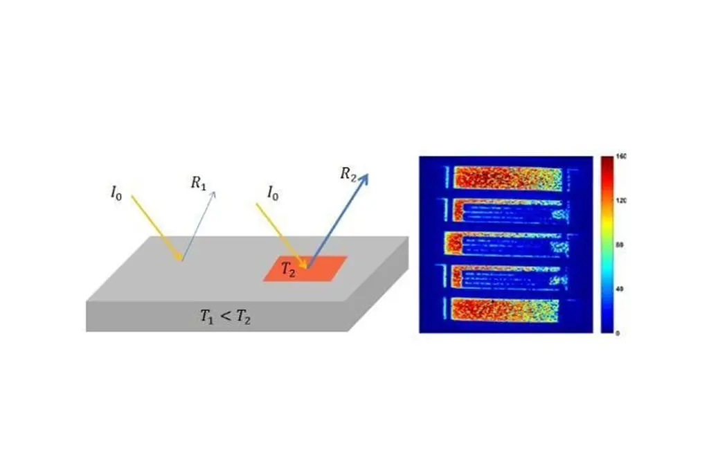
TTI exploits of the linear effect that the temperature has on the surface reflectivity (Eq. 1).

Thermoreflectance Thermal Imaging

Change of the intensity (reflectivity) due to the temperature

As illustrated is the figure, when the sample is irradiated the intensity of the reflected beam depends on the local temperature of the irradiated zone. Thus hot spots, as the red square in the figure, increase the intensity of the reflected beam. Therefore, the accurate analysis of the reflected beam at the selected areas provides a thermal map of the device surface.

Practical Applications:

This mapping technique provides useful information about the power dissipation profile and hot spots related to the design of microelectronics devices. Besides it is also used for the early detection of design, manufacturing or material defects in microelectronics systems.

Thermoreflectance Thermal Imaging

Appl Phys., 2006; 39: 4153-4166

Optical and thermal image of heating resistor

The figure illustrates the compare an optical and a thermal image of a five broad polysilicon resistive stripes (heaters). Thanks to this technique it is possible to obtain the temperature map placed at the right of the image. This image results from an accumulation over 200 heating periods and a total acquisition time of 1 min in practice.

To illustrate the high spatial resolution and the detection of micrometric hot spots the following image also shows the thermal analysis of high power semiconductor laser bars. In this case it is clearly observed a micrometric hot spot at the face of one emitter (x = 225µm). This permitted the early detection of the ongoing mirror degradation, which eventually leads to catastrophic optical mirror damage failure.

Thermoreflectance Thermal Imaging

Appl Phys., 2018; 51: 013001

Thermal imaging of an emitter laser bar

The spatial and temperature resolutions and sensitivity reached by thermoreflectance techniques are excellent, however the accuracy of the absolute temperature readings is more difficult to evaluate due to the lack of comparable thermal techniques with submicrometric spatial resolution. Therefore, major applications of the technique on the microelectronics field, involves analyzing the relative temperature gradients on the surface devices and similar studies such as thermal mapping applications, thermal transport studies and hot spots analyses.

On the other hand, thanks to the high time resolution, ITT is also used for transient thermal imaging in switching devices or other systems under pulsed operation. This character is normally used to identify buried defects or help to extract the thermal resistance/capacitance network in the device, surrounding regions in the substrate and the package.

Thermoreflectance Thermal Imaging

Proceeding 26th IEEE SEMI-THERM Symposium 978-1-4244-6460-9/10

Time domain thermoreflectance imaging of a gold heater

The figure show quick heat diffusion in the device metal on short and long time scale thermal imaging of a 100 micron integrated gold heater using pulsed boxcar averaging. The figure also illustrates how the technique is used to study the transitory heat transmission from the sample to other adjacent components.

Related

Recent Posts

Modeling Fringing Field Losses in Inductors & Transformers

30.4.2026
6

YMIN Introduces Polymer Tantalum Capacitors for AI Server SSDs

29.4.2026
13

Miniaturization of Tantalum Capacitors: Structural Limit Under Constant Rating

27.4.2026
25

Heatsink Design and Thermal Interface Materials for Reliable Electronics

27.4.2026
8

Murata New MLCC Bulk Case Packaging Cuts Packaging Material by 99%

27.4.2026
44

Exxelia Introduces SMD High‑Voltage Mica Capacitors

28.4.2026
19

Modelithics Releases COMPLETE v26.1 for Keysight ADS

23.4.2026
13

April 2026 Interconnect, Passives and Electromechanical Components Market Insights

22.4.2026
75

KYOCERA AVX Introduces Traction‑Grade DC Link Film Capacitors

21.4.2026
47

Upcoming Events

May 5
16:00 - 17:00 CEST

Understanding and Selecting Capacitors – Fundamentals, Technologies and Latest Trends

May 7
17:00 - 18:00 CEST

From Grid to Motion: How Industrial Electrification is Redefining Power System Design

May 12
8:00 - 15:00 CEST

ESCC Space Splice connectors

View Calendar

Popular Posts

  • Buck Converter Design and Calculation

    0 shares
    Share 0 Tweet 0
  • Boost Converter Design and Calculation

    0 shares
    Share 0 Tweet 0
  • Flyback Converter Design and Calculation

    0 shares
    Share 0 Tweet 0
  • LLC Resonant Converter Design and Calculation

    0 shares
    Share 0 Tweet 0
  • MLCC and Ceramic Capacitors

    0 shares
    Share 0 Tweet 0
  • Dual Active Bridge (DAB) Topology

    0 shares
    Share 0 Tweet 0
  • What Electronics Engineer Needs to Know About Passive Low Pass Filters

    0 shares
    Share 0 Tweet 0
  • Capacitor Charging and Discharging

    0 shares
    Share 0 Tweet 0
  • MLCC Case Sizes Standards Explained

    0 shares
    Share 0 Tweet 0
  • Ripple Current and its Effects on the Performance of Capacitors

    3 shares
    Share 3 Tweet 0

Newsletter Subscription


Passive Components Blog

© EPCI - Leading Passive Components Educational and Information Site

  • Home
  • Privacy Policy
  • EPCI Membership & Advertisement
  • About

No Result
View All Result
  • Home
  • Knowledge Blog
  • PCNS

© EPCI - Leading Passive Components Educational and Information Site

This website uses cookies. By continuing to use this website you are giving consent to cookies being used. Visit our Privacy and Cookie Policy.
Go to mobile version