Passive Components Blog
No Result
View All Result
  • Home
  • NewsFilter
    • All
    • Aerospace & Defence
    • Antenna
    • Applications
    • Automotive
    • Capacitors
    • Circuit Protection Devices
    • electro-mechanical news
    • Filters
    • Fuses
    • Inductors
    • Industrial
    • Integrated Passives
    • inter-connect news
    • Market & Supply Chain
    • Market Insights
    • Medical
    • Modelling and Simulation
    • New Materials & Supply
    • New Technologies
    • Non-linear Passives
    • Oscillators
    • Passive Sensors News
    • Resistors
    • RF & Microwave
    • Telecommunication
    • Weekly Digest

    Bourns Release Automotive 4-Terminal Shunt Resistors

    Bourns Releases High Inductance Common Mode Choke

    Vishay Releases Automotive TO-220 Case 50W Thick Film Power Resistor

    High Energy Density Polymer Film Capacitors via Molecular and Interfacial Design

    Bourns Releases High Clearance and Creepage 1500VDC Power Transformer

    KYOCERA AVX Expands Stacked MLCC Capacitors Offering

    Murata and QuantumScape Joint Development for Solid Batteries Ceramic Separators

    YAGEO Unveils Compact 3.6kW LLC Transformer for OBC EV Charging

    Over-Voltage Protection Clippers, Clampers, Snubbers, DC Restorers

    Trending Tags

    • Ripple Current
    • RF
    • Leakage Current
    • Tantalum vs Ceramic
    • Snubber
    • Low ESR
    • Feedthrough
    • Derating
    • Dielectric Constant
    • New Products
    • Market Reports
  • VideoFilter
    • All
    • Antenna videos
    • Capacitor videos
    • Circuit Protection Video
    • Filter videos
    • Fuse videos
    • Inductor videos
    • Inter-Connect Video
    • Non-linear passives videos
    • Oscillator videos
    • Passive sensors videos
    • Resistor videos

    Connector PCB Design Challenges

    Efficient Power Converters: Duty Cycle vs Conduction Losses

    Ripple Steering in Coupled Inductors: SEPIC Case

    SEPIC Converter with Coupled and Uncoupled Inductors

    Coupled Inductors in SEPIC versus Flyback Converters

    Non-Linear MLCC Class II Capacitor Measurements Challenges

    Percolation Phenomenon and Reliability of Molded Power Inductors in DC/DC converters

    Root Causes and Effects of DC Bias and AC in Ceramic Capacitors

    How to Calculate the Output Capacitor for a Switching Power Supply

    Trending Tags

    • Capacitors explained
    • Inductors explained
    • Resistors explained
    • Filters explained
    • Application Video Guidelines
    • EMC
    • New Products
    • Ripple Current
    • Simulation
    • Tantalum vs Ceramic
  • Knowledge Blog
  • Suppliers
    • Who is Who
  • PCNS
    • PCNS 2025
    • PCNS 2023
    • PCNS 2021
    • PCNS 2019
    • PCNS 2017
  • Events
No Result
View All Result
Passive Components Blog
No Result
View All Result

Thin Film Resistors Extend Frequency Coverage in Small Form Factors

28.11.2018
Reading Time: 4 mins read
A A

Source: Microwave journal news

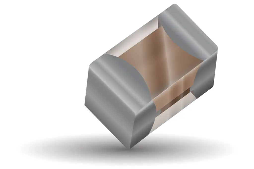
by AVX Corp., Fountain Inn, S.C. The electronics industry continues to push manufacturers to develop smaller passive components capable of higher frequency performance. To meet these demands, traditional passive component designs are being stretched to beyond their limits. AVX recently pushed the boundary of traditional high frequency resistors with its new UBR series ultra-broadband thin film resistors. These ruggedly constructed, ultraminiature (EIA 0402, 1005 metric), ultra-broadband resistors are made with high performance tantalum nitride materials. The substrate and cover use the company’s proprietary, automotive-qualified, glass-sandwich FLEXITERM®surface-mount technology, instead of the typical alumina ceramic or aluminum nitride, which reduces the traditional relative permittivity to just 4.4 F/m and helps extend the frequency range to 20 GHz.

RelatedPosts

Bourns Release Automotive 4-Terminal Shunt Resistors

Bourns Releases High Inductance Common Mode Choke

Vishay Releases Automotive TO-220 Case 50W Thick Film Power Resistor

The innovative design of the FLEXITERM termination provides an extra measure of protection against flexure damage during installation, and the parts are also 100 percent laser trimmed, allowing tight tolerances. Although this extension comes at the cost of overall power handling, the new UBR series ultra-broadband resistors offers a 125 mW power rating. The power rating and the wider frequency range make them ideal for use in optoelectronic, automotive, telecom, broadband and SATCOM systems, including optoelectronic transceiver modules, transmit and receive optical subassemblies, wideband test equipment, low noise amplifiers, mixers, broadband receivers, EW jammers, directional couplers and ultra-broadband splitters and combiners.

figure 1

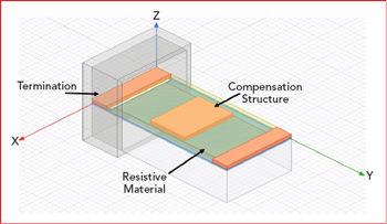
Figure 1 Exploded view of a UBR series resistor with AVX’s patented transmission line compensation.

The UBR series resistors are offered in the following configurations:

  • Four standard temperature coefficient of resistance values: ±25, ±50, ±100 and ±250 ppm/°C, with additional values available when requested. The rated operating temperature is from −40°C to +125°C.
  • Four standard resistance values: 25, 50, 100 and 200 Ω, with the range from 20 to 200 Ω also available if requested.
  • Three standard tolerances: ±0.5, ±1 and ±2 percent, with additional values available.
  • Two termination options: FLEXITERM Ag/epoxy, plated with NiSn, or gold-plated nickel (Ni/Au). They are RoHS compliant.

The 0402 resistors measure 1 mm long × 0.5 mm wide × 0.5 mm high with ±0.10 mm tolerance and have a terminal width of 0.25 mm ±0.15 mm. They are packaged on tape-and-reel for automated assembly.

EXTENDING THE FREQUENCY RESPONSE

While this innovation in resistor design allows more passive components to be used at higher frequencies, continued innovation is required to achieve greater performance in the ever-smaller packages demanded. One way to extend the performance of a traditional resistor is to add transmission line compensation on the board. This improves resistor performance by countering some of the parasitic of the resistor and the board it is mounted on; however, this takes valuable board space.

Figure 2

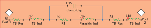
Figure 2 Equivalent circuit of the UBR series resistor with the transmission line compensation structure, mounted on a test board with a 50 Ω line.

figure 3

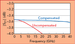
Figure 3 Comparison of the simulated |S21| of compensated and uncompensated UBR series resistors on a 50 Ω grounded coplanar transmission line on a Rogers 4350 test board.

To resolve this issue, AVX has created a UBR series resistor with a patented, built-in compensation structure that emulates the effect of compensating the transmission line without taking additional space (see Figure 1). The equivalent circuit of the UBR series resistor with the added transmission line compensation structure with a 50 Ω line on a test board is shown in Figure 2. This circuit is better matched to the 50 Ω line than a standard broadband resistor, thanks to the added capacitance across the resistor and the modified input and output transmission line equivalents, which achieve better matching to higher frequencies. Figure 3 shows a simulation using ANSYS HFSS 19.1 software, comparing the |S21| of the uncompensated and compensated UBR series resistors, both the same value and mounted on a 50 Ω grounded coplanar transmission line on a Rogers 4350 test board. The response of the resistor with the optimized compensation structure through 40 GHz looks like an “ideal” resistor (assuming ±10 percent tolerance, i.e., where the resistor value is between 45 and 55 Ω), while the response of the non-optimized resistor only extends to 15 GHz.

figure 3

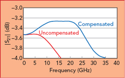
Figure 4 Comparison of the simulated |S21| of compensated and uncompensated UBR series resistors on a 50 Ω coplanar line on an alumina board.

To extend the resistor’s frequency range, it is important to know the specific board characteristics, as different boards require different compensation structures to optimize high frequency performance. To illustrate, when the Rogers 4350 test board in this simulation is changed to an alumina board with a 50 Ω grounded coplanar line, the compensation structure needs to be modified to match the parasitics of the new transmission line and board. Figure 4 shows the |S21| responses on the alumina board, comparing the standard UBR resistor with the resistor compensated for the alumina board. The compensated response extends to almost 30 GHz, versus just 12.5 GHz for the uncompensated resistor.

Each application is likely to require a unique board design and set of parameters. While some designs may require tighter tolerance on the swing of |S21| versus frequency, others may require higher frequency performance. Matching each individual requirement only using modeling software will miss some parasitics a real world board will add. To help ease the design load, AVX has several stepped values of typical compensation structures available in a kit that design engineers can use to identify the designs that best extend the frequency range of a given circuit while minimizing board space. The design kit helps assure that the correct compensation is achieved, saving time chasing performance issues through multiple board spins. This is especially beneficial where board space and vendor designs are set and qualified and need to match tight design and performance requirements and strict regulations, such as military and medical applications.

The new compensated UBR series resistors are now being released, with additional improvements underway. Future developments will shrink the component size from 0402 to 0201, increase the power rating toward 1 W and add new termination styles to meet a wider variety of customer needs.

Related

Recent Posts

Bourns Release Automotive 4-Terminal Shunt Resistors

17.10.2025
9

Vishay Releases Automotive TO-220 Case 50W Thick Film Power Resistor

16.10.2025
7

KYOCERA AVX Expands Stacked MLCC Capacitors Offering

14.10.2025
29

YAGEO Unveils Compact 3.6kW LLC Transformer for OBC EV Charging

13.10.2025
125

KYOCERA Releases Shielded Board-to-Board Connectors for Reliable EMI Protection

13.10.2025
24

Silicon Capacitors Market: Shaping the Foundation for Next-Gen Miniaturization Electronics

10.10.2025
53

Enhancing Energy Density in Nanocomposite Dielectric Capacitors

9.10.2025
35

Advances in the Environmental Performance of Polymer Capacitors

8.10.2025
63

Researchers Demonstrated High Energy Ceramic Capacitors Stable in Wide Temperature Range

2.10.2025
27

Stackpole Offers High Voltage Plate Resistors up to 40KV

2.10.2025
31

Upcoming Events

Oct 20
October 20 - October 23

Digital WE Days 2025 – Virtual Conference

Oct 21
October 21 @ 12:00 - October 23 @ 14:15 EDT

Space and Military Standards for Hybrids and RF Microwave Modules

Oct 28
8:00 - 15:00 CET

Power Up Your Design: SN6507 and the Ready-to-Use Development Kit

View Calendar

Popular Posts

  • Buck Converter Design and Calculation

    0 shares
    Share 0 Tweet 0
  • Boost Converter Design and Calculation

    0 shares
    Share 0 Tweet 0
  • Flyback Converter Design and Calculation

    0 shares
    Share 0 Tweet 0
  • LLC Resonant Converter Design and Calculation

    0 shares
    Share 0 Tweet 0
  • Ripple Current and its Effects on the Performance of Capacitors

    3 shares
    Share 3 Tweet 0
  • What is a Dielectric Constant and DF of Plastic Materials?

    4 shares
    Share 4 Tweet 0
  • SEPIC Converter Design and Calculation

    0 shares
    Share 0 Tweet 0
  • MLCC and Ceramic Capacitors

    0 shares
    Share 0 Tweet 0
  • Dual Active Bridge (DAB) Topology Explained

    0 shares
    Share 0 Tweet 0
  • Flying Capacitors

    0 shares
    Share 0 Tweet 0

Newsletter Subscription


Passive Components Blog

© EPCI - Leading Passive Components Educational and Information Site

  • Home
  • Privacy Policy
  • EPCI Membership & Advertisement
  • About

No Result
View All Result
  • Home
  • Knowledge Blog
  • PCNS

© EPCI - Leading Passive Components Educational and Information Site

This website uses cookies. By continuing to use this website you are giving consent to cookies being used. Visit our Privacy and Cookie Policy.
Go to mobile version