Source: Kemet Engineering Center blog
Capacitors are increasingly being recognized for having the potential to improve efficiency and, therefore, power density. Read the next article by Kemet Engineering Center about the ceramic technology guidelines for high power density circuits.
The amount of data we’re generating today is mind-blowing. In the last couple of years 90 per cent of the data in the world was generated, and we’re creating over 2.5 quintillion bytes of data every day. This means that there will be 40x more bytes of data than there are stars in the observable universe by 2020! All this data relies on electrical power. And, the internet of things, and adoption of hybrid-electric vehicles is only going to accelerate this demand.
Engineers are continually seeking ways to make devices more efficient to conserve the amount of power we need. Switching semiconductor devices have been the main focus for increasing efficiency and power density as they significantly contribute towards dynamic and static losses in any power system. However, it is becoming ever more expensive and challenging to achieve incremental improvements. Capacitors are increasingly being recognized for having the potential to improve efficiency and, therefore, power density.
There are three areas in power design where capacitors can positively impact the efficiency of the system, each have a slightly different requirement from the capacitor:
- DC-LINK requires high voltages, temperatures, frequencies, and high ripple current
- Snubbers can require high dV/dTs, high ripple currents, high voltages, and high temperatures as well as low inductance.
- Resonant converters need high ripple currents, a wide operating voltage range, and capacitance stability over temperature, DC and AC voltage.
Combining these requirements demands a capacitor with very low loss, high ripple current handling capabilities, the ability to withstand high voltages and accept higher operating temperatures while exhibiting stable capacitance and high mechanical stability. Let’s look at which capacitor packages can deliver this.
Class I vs Class II Multilayer Ceramic Capacitors (MLCCs)
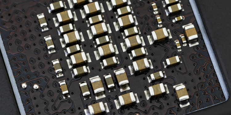
MLCCs exhibit key properties that are ideal for snubber, DC-LINK, and resonant applications. MLCCs are built from alternating layers of ceramic dielectric and metal electrodes and are predominantly manufactured using Base Metal Electrodes (BME). They typically have Nickel electrode s and a CaZrO3 dielectric for Class I or BaTiO3 dielectric for Class II as seen in figure 1.

Figure 1: Exploded View of a Base Metal Electrode MLCC
How stable is the dielectric?
Dielectrics are classified by their capacitance stability over temperature. Class I – C0G, NPO, U2J – contains the most temperature stable dielectrics, but these have the lowest dielectric constant (K). Therefore, a higher volume is needed to achieve the same capacitance as Class II MLCC types.
Class II dielectric materials – X7R and X5R – have mid-range temperature stability and values of K. Class II MLCCs provide a much higher capacitance per unit volume compared to Class I. But, as Class II MLCCs use a BaTiO3 dielectric there are some characteristics that can drastically influence their use in power applications. For example, capacitance can be affected by the operating temperature, applied DC bias, and time after last heat (aging).
The Temperature Coefficient of Capacitance (TCC) is the stability of capacitance vs temperature and is determined by the Electronics Industries Alliance (EIA) dielectric classification such as “X7R”. X7R has an operating temperature range of -55oC to 125oC with maximum capacitance limits of ±15%. Whereas, X5R has an operating temperature range of -55oC to 85oC with the same ±15% capacitance limits.
Stability of capacitance vs voltage (VCC) has no EIA definition. However, users can see a decrease in capacitance of up to 80% at rated voltage for higher capacitance Class II MLCCs. This VCC characteristic also varies widely between manufacturers.
In addition, capacitance can also decrease due to ageing – or time after last heat. It is usually between 2-5% per decade hour after the last heat above 130oC, which is typically when soldering the parts during the manufacturing process.
In comparison, Class I dielectrics are much more stable, making them the perfect choice for resonant applications such as wireless charging circuits and LLC resonant converters. For example, C0G has a slight capacitance shift of 30ppm/°C, or 0.3% at 125oC, while U2J has 750ppm/°C or 7.5% at 125oC but is linear and predictable. Both C0G and U2J have negligible capacitance change vs DC bias and almost no change vs time (aging).
Importance of Equivalent Series Resistance
Equivalent Series Resistance (ESR) is also a vital characteristic to consider for capacitors in power applications due to i2R losses. BaTiO3 is a ferroelectric material, and as such it can create domain regions within the dielectric and domain wall heating and higher ESR compared to Class I dielectrics. It’s common for Class II MLCCs to have an ESR that is up to two orders of magnitude higher than Class I MLCCs. An example of ESR for Class I C0G/U2J MLCCs and Class II X7R can be seen in figure 2.

Figure 2: ESR Comparison Between Class II X7R and Class I C0G/U2J
High ESR from the high AC in power applications results in excessive heating. Figure 3 shows that X7R increases by 40oC with just 5Arms, whereas C0G and U2J dielectrics experience a self-temperature rise of approximately 15oC at 10Arms.

Figure 3: Ripple Current Comparison Between Class II X7R and Class I C0G/U2J

Figure 4: Key Characteristics Comparison Between Class II X7R and Class I C0G/U2J
Class I technologies come out on top
It is clear to see that Class I BME dielectric based MLCCs including C0G and U2J have high temperature stability, low loss and high ripple current capability, and stand out as the ideal choice for high power density applications. Their performance is predictable, and designers can achieve fine tolerances.
At KEMET we have created numerous product ranges specifically designed to improve power conversion efficiencies. These include C0G High Voltage Commercial and Automotive Grades series of capacitors, the surface mount KC-LINKTM 3640 220nF 500V ceramic capacitor, and KONNEKTTM – an innovative leadless multi-chip solution design for high efficiency and high-density power applications.
But what are the latest Class I solutions? Here we’ll delve deeper into Class I technologies that are enabling engineers to make their devices more efficient.
KC-LINKTM
We have recently introduced the surface mount KC-LINKTM 3640 220nF 500V capacitors which are designed specifically to meet the growing demand for fast switching semiconductors that operate at higher voltages, temperatures, and frequencies. The ceramic capacitor uses a CaZrO3 dielectric material and provides a very low-loss solution with ESR values below 4mW from 40kHz to 1MHz and as low as 2mW around 50kHz. This allows for typical ripple currents around 20Arms from 50kHz to 300kHz at 0V DC bias at 105°C ambient.
In addition to KC-LINK’s excellent power handling capability, it’s CaZrO3 dielectric also boasts almost a 2x Modulus of Rupture (MOR) compared to Class II BaTiO3 dielectrics. This gives KC-LINKTM high mechanical robustness and negates the need for a lead frame, thus creating a very low inductance solution (<1nH). With an operating temperature of 150oC, these MLCCs can be mounted near the wide bandgap (WBG) power switches with little need for cooling conserving power and increasing efficiency. Figure 1 shows its impedance, ESR and ripple current.


Figure 1: KC-LINKTM Impedance, ESR, and Ripple Current
KONNEKTTM technology
Applications often require higher levels of capacitance than high performance Class I dielectrics can achieve, and this requires increased board area. But, with increasing board area comes a reduced power density of the solution. We have developed KONNEKTTM technology – a leadless multi-chip solution design for high efficiency and high-density power applications – precisely to address this problem. KONNEKTTM uses transient liquid phase sintering (TLPS) process to combine Class I MLCCs which can be mounted using standard reflow practices.
Let’s take a look at an example of how this technology is providing high power handling capability:
Three U2J 0.47mF 50V 1812 MLCCs can be joined in ‘standard orientation’ using KONNEKTTM technology and provide a capacitance of 1.4mF in the same footprint as a single MLCC, as shown in figure 2. Further benefits can be achieved by placing the assembly on its side – known as ‘low-loss orientation’ – whereby lower ESR, lower thermal resistance and inductance (ESL), and ultimately higher power handling capability can be achieved.

Figure 2: (Top) KONNEKTTM Technology for Increasing Capacitance in the Same Footprint (Bottom) Standard vs Low-Loss Orientation
Using the three-MLCC 1.4mF module based on the U2J dielectric, ESL is 1.6nH when mounted in standard orientation, reducing to just 0.4nH in low-loss orientation. Similarly, the ESR is reduced in low-loss orientation (from 1.3mW to 0.35mW) which reduces system losses and limits the temperature rise in the component.
Furthermore, during a ripple current test at 20Arms, infra-red thermal imaging has shown a temperature of 65°C for standard orientation but only 35°C in the low-loss orientation, as can be seen in Figure 3. As a result, current handling is reduced to 11.0Arms in standard orientation, while 34.0Arms is achievable with low-loss orientation.
With very low ESR and extremely high ripple currents, the KONNEKTTM U2J capacitor is ideal for LLC resonant converters specifically designed for data centers, wireless charging, and automotive applications. In the low loss orientation less electrical energy is converted to heat so improving energy efficiency.

Figure 3: (Left) KONNEKT U2J Thermal Imaging Comparing Standard/Traditional vs Low-Loss Orientation During 20Arms ripple current. (Right) Electrical Characteristics
Energy efficiency is high on the agenda in today’s world as it reduces operating costs for significant power usage including automobiles and data center applications. Most of the development effort to date has focused on circuit topologies and semiconductor performance, but passive components such as capacitors are now proving that they have a significant positive impact on power efficiency.
At KEMET we’re dedicated to researching technologies that further increase power handling capability, thereby enabling power engineers to improve efficiencies of their systems.


