• Latest
  • Trending
  • All
  • Capacitors
  • Resistors
  • Inductors
  • Filters
  • Fuses
  • Non-linear Passives
  • Applications
  • Integrated Passives
  • Oscillators
  • Passive Sensors
  • New Technologies
  • Aerospace & Defence
  • Automotive
  • Industrial
  • Market & Supply Chain
  • Medical
  • RF & Microwave
  • Telecommunication

Snubber Capacitors Functionality and Selection Guide

24.8.2022

Investigating Modeling Techniques of Class II Ceramic Capacitors Losses for High Voltage and Current Applications

15.3.2023

TDK Extends Range of Industrial Single Pair Ethernet (SPE) Inductors

15.3.2023

Premo Unveils New series of 11kW 3-Phase On-Board Charger Transformers

15.3.2023

TAIYO YUDEN Releases 150C Automotive Power Inductors

15.3.2023

TAIYO YUDEN Announces Completion of MLCC Material Building

15.3.2023

TDK’s High-Impedance Multilayer Common Mode Filters Mitigates Noise Issues in Automotive Interfaces

14.3.2023
  • Home
  • Privacy Policy
  • EPCI Membership & Advertisement
  • About
No Result
View All Result
NEWSLETTER
Passive Components Blog
  • Home
  • NewsFilter
    • All
    • Aerospace & Defence
    • Antenna
    • Applications
    • Automotive
    • Capacitors
    • Circuit Protection Devices
    • Filters
    • Fuses
    • Inductors
    • Industrial
    • Integrated Passives
    • Market & Supply Chain
    • Medical
    • New Materials & Supply
    • New Technologies
    • Non-linear Passives
    • Oscillators
    • Passive Sensors
    • Resistors
    • RF & Microwave
    • Telecommunication

    Investigating Modeling Techniques of Class II Ceramic Capacitors Losses for High Voltage and Current Applications

    TDK Extends Range of Industrial Single Pair Ethernet (SPE) Inductors

    Premo Unveils New series of 11kW 3-Phase On-Board Charger Transformers

    TAIYO YUDEN Releases 150C Automotive Power Inductors

    TAIYO YUDEN Announces Completion of MLCC Material Building

    TDK’s High-Impedance Multilayer Common Mode Filters Mitigates Noise Issues in Automotive Interfaces

    Sumida Introduces Unshielded High-Inductance Inductors

    Cornell Dubilier Announces Low Inductance DC Link Film Capacitors

    Bourns Introduces Automotive Resettable TCO Thermal Cut-off Protection Device

    Trending Tags

    • Ripple Current
    • RF
    • Leakage Current
    • Tantalum vs Ceramic
    • Snubber
    • Low ESR
    • Feedthrough
    • Derating
    • Dielectric Constant
    • New Products
    • Market Reports
  • VideoFilter
    • All
    • Antenna videos
    • Capacitor videos
    • Filter videos
    • Fuse videos
    • Inductor videos
    • Non-linear passives videos
    • Oscillator videos
    • Passive sensors videos
    • Resistor videos
    • Sensors

    Investigating Modeling Techniques of Class II Ceramic Capacitors Losses for High Voltage and Current Applications

    Understanding Basics of Current Sense Resistors

    What Decoupling Capacitor Value To Use And Where To Place Them

    How to Measure Rated Current on Power Inductors

    LTspice Simulation of a Spark-Gap Circuit Protection Surge Arrester

    Approximate Inductor Design Using Two Alternative Cores

    1kW Phase Shift Full Bridge Converter Design and Simulation

    Multiphase Buck Trans-Inductor Voltage Regulator (TLVR) Explained

    Smart Power Distribution Unit Architecture and Inductor Losses

    Trending Tags

    • Capacitors explained
    • Inductors explained
    • Resistors explained
    • Filters explained
    • Application Video Guidelines
    • EMC
    • New Products
    • Ripple Current
    • Simulation
    • Tantalum vs Ceramic
  • Knowledge Blog
  • Suppliers
    • Preferred Suppliers
    • Who is Who
  • Events
No Result
View All Result
Passive Components Blog
No Result
View All Result

Snubber Capacitors Functionality and Selection Guide

24.8.2022
Reading Time: 12 mins read
0 0
0
SHARES
10.2k
VIEWS

Paul Rako at Electronic Design’s article describes snubber capacitors functionality to reduce the spikes in converter design, protecting the transistors and reducing EMI. The article also provides some recommendations on snubber capacitor type selection.

A snubber circuit limits voltage spikes in power converters.

RelatedPosts

TDK Releases its Application Guide on Motor/Inverter Circuit Configuration

What Ceramic Technologies Are Best for High Power Density Applications?

KEMET’s New KC-LINK™ SMD Ceramic Capacitors Series Offers Industry Leading Performance for Fast Switching Wide Bandgap Semiconductor Applications

Snubbers are also used in the output of Class-D audio amplifiers for the same reasons (Fig. 1).

1. A snubber network damps the ringing and overshoot due to fast switching of high currents. (Courtesy of Cirrus Logic)
Figure 1. A snubber network damps the ringing and overshoot due to fast switching of high currents. (Courtesy of Cirrus Logic)

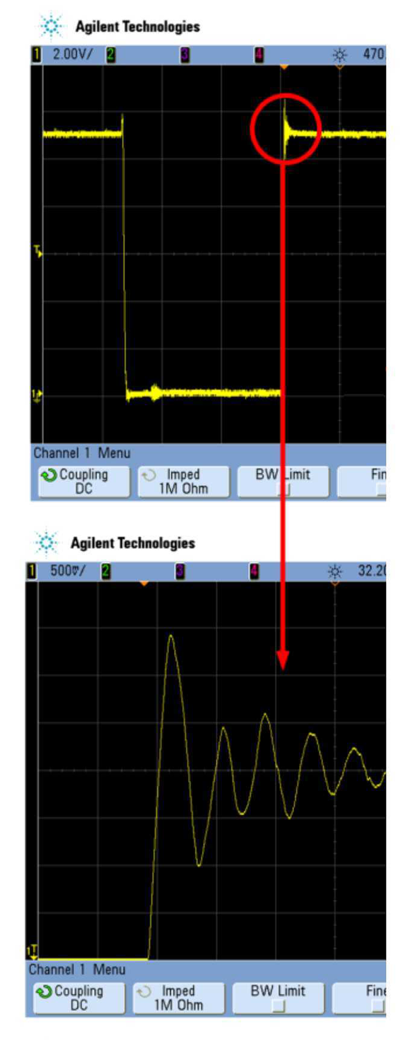
When the transistor you use to switch the current turns off, it generates a high-voltage spike that could damage the device.

This spike will also generate electromagnetic interference (EMI). Be aware that EMI is caused by current in a loop. If your snubber network routes current in a large loop, it will increase rather than reduce EMI.

It’s All About Inductance

The voltage spikes in your circuit are caused by discrete inductors that you’re switching. The leakage inductance of transformers looks like a series inductance with the ideal transformer winding, and that will generate voltage spikes. These discrete inductances are obvious looking at your schematic. A further problem is all of the stray inductance in the wires and printed-circuit-board (PCB) traces. Any wire in space has inductance. Power electronics design is like RF design, where your circuit board is a component.

The fact that the layout and construction of your PCB changes stray inductance means you will need to build and test your power designs to optimize them. This is usually faster and cheaper than using a field solver to figure out the stray inductance while in the design phase. Looking at similar designs can give you an idea of the sizes of the snubber components to start with.

How to Snub Your Spikes

The simplest snubber network is a series RC circuit at the switch node (Fig. 2). The capacitor prevents dc currents from flowing. When the transistor switches, the capacitor then tends to look like a short circuit and the resistor can shunt current out of the switch node. One disadvantage of the RC snubber is that it also adds to the current the transistor must carry when it turns on—it doesn’t distinguish between the switch node voltage rising or falling.

2. An RC snubber network adds a resistor and capacitor in series to the high-speed switch node of your circuit. (Courtesy of Cornell Dubilier)
Figure 2. An RC snubber network adds a resistor and capacitor in series to the high-speed switch node of your circuit. (Courtesy of Cornell Dubilier)

For higher power application, you can put a diode in series with the RC to create an RCD snubber (Fig. 3). The diode blocks any current in the network as the transistor turns on. When the transistor turns off, the diode forward-biases, and current flows through the resistor and capacitor.

3. An RCD snubber network uses a diode to steer the current so that power isn’t wasted during switch turn-on. (Courtesy of Cornell Dubilier)
Figure 3. An RCD snubber network uses a diode to steer the current so that power isn’t wasted during switch turn-on. (Courtesy of Cornell Dubilier)

See also article: RC snubber design for SMPS protection.

Snubber Design

Cornell Dubilier has a good guide on designing snubber networks. The guide has a quick design section with the very analog suggestion, “Plan on using a 2-watt carbon composition resistor.” The guide notes that wire-wound resistors will cause problems since they have higher inductance. Even a metal film resistor might have problems if trimming is done in a spiral shape that has inductance. Since this is analog, you can be confident a 2-W resistor isn’t appropriate for a 1-W wall-wart or a 10-kW power inverter. But it’s a nice place to start.

The guide runs through a quick design method, and then does an optimized design that reduces the resistor power rating by a factor of 5, and the snubber capacitor value by a factor of 3.5. Those gains are for a specific design with a specific PCB layout; yours is sure to differ.

One valuable observation in the guide is that the switch node you’re trying to snub will have a characteristic impedance, just like a transmission line. You want to size the snubber resistor no larger than that characteristic impedance so that there’s no voltage transient when the transistor switch opens.

A nice thing about the resistor in the RC network is that you can measure across it with a differential scope probe to see the instantaneous currents that are also in the capacitor. With an RCD network, you have to put a current probe around the capacitor lead. This will be tricky with surface-mount devices, but you can usually hack in a wire loop in order to get a current probe in the circuit. These are all fast signals, so be sure to have an oscilloscope and probes with sufficient bandwidth to measure the true peak currents and voltages.

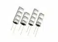
The Problem with Electrolytics

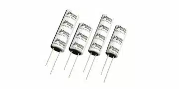
Experienced analog engineers know there are many differences in capacitor types. No physical capacitor is a perfect representation of the symbol of your schematics or the model in your Spice simulation. Aluminium electrolytic capacitors come in large values and are cheap. With that diode in your RCD snubber network, you will be able to get around the problem that electrolytic capacitors have a polarity, and they will explode if you subject them to reverse polarity.

Despite this, electrolytic capacitors aren’t best suitable for snubber networks since snubbers have very high peak currents that would self-heat and damage an electrolytic capacitor. Worse yet, aluminium wet electrolytic capacitors have terrible reliability and conventional MnO2 tantalum capacitors are sensitivity to high power surges. This make aluminium and tantalum electrolytic a poor choice for snubber circuits.

Mica and Film Capacitors

A nice feature of the Cornell Dubilier guide is that the company is semi-agnostic about the type of capacitor you use. The guide initially recommends you look at a mica capacitor. Mica does get close to the perfect capacitor for a lot of parameters. Unfortunately, they only come in low values and tend to be expensive.

4. Film capacitors can be either be a foil or metallized type. Foil types use a discrete layer of metal, whereas the metallized types have the metal plated on the film. (Courtesy of Wikimedia)
Figure 4. Film capacitors can be either be a foil or metallized type. Foil types use a discrete layer of metal, whereas the metallized types have the metal plated on the film. (Courtesy of Wikimedia)
5. Some foil film capacitors use thicker foil near the electrodes to allow greater peak currents. (Courtesy of Wikimedia)
Figure 5. Some foil film capacitors use thicker foil near the electrodes to allow greater peak currents. (Courtesy of Wikimedia)

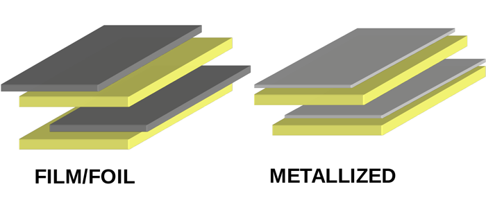
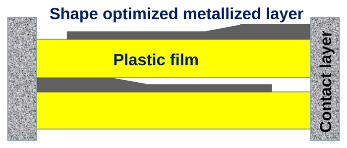
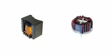
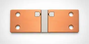
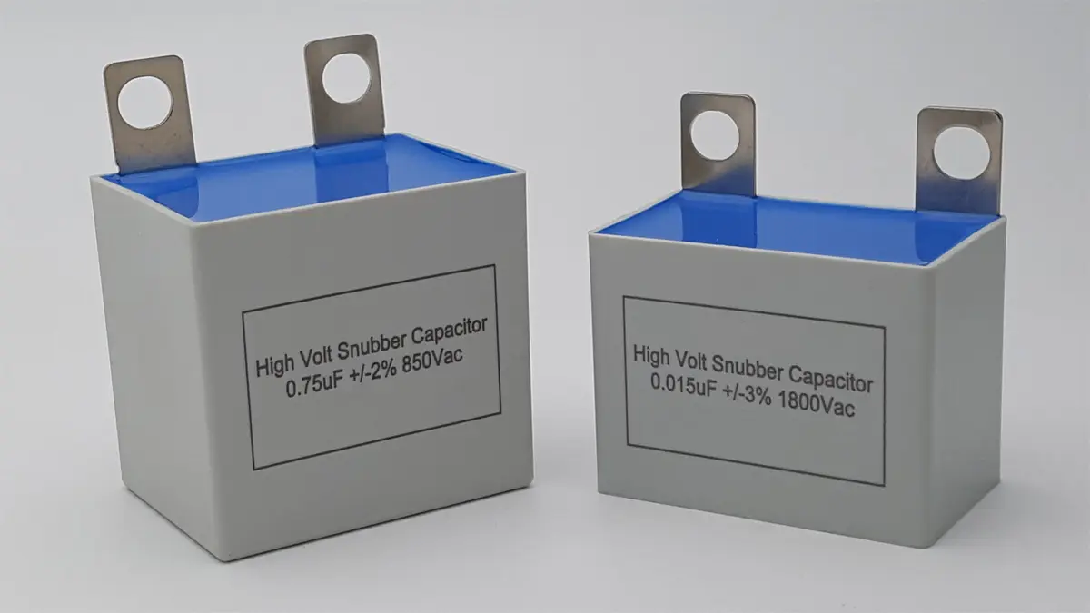
In lieu of mica capacitors, your snubber could use film capacitors. These are both wound foil film types and metallized film types (Fig. 4). The foil types take higher peak currents. The film types will “heal” after an overvoltage, when the plastic film just melts away from the short-circuit pinhole. Some foil types have varying thickness of the foil to further increase current capacity while reducing physical size (Fig. 5). Polypropylene film is preferred since polyester has higher losses, making it unsuitable for snubber networks.

Dielectrics: Friend and Foe

With small size and ruggedness, you might consider ceramic capacitors in snubber networks. Be careful of the capacitor’s peak current rating, which you can never exceed, even momentarily. Ceramics and metallized film will also have a transient-voltage limitations, perhaps as low as 50 V/ns. With the much faster switching times of silicon-carbide (SiC) and gallium-nitride (GaN) power transistors, you should be sure you’re not exceeding the transient withstanding capability of the snubber capacitor.

Another problem with ceramic capacitors class II dielectric is that they can lose capacitance with temperature, applied voltage and DC BIAS Ageing. This is a function of the dielectrics used by the component type. A C0G dielectric has very good temperature stability, but it’s only available in small values and costs significantly more than other dielectrics.

Ceramic Capacitors Do Work

Despite the peculiarities of ceramic capacitors, you can use them in snubbing networks as long as you understand their advantages and limitations. Murata describes how different dielectrics are suitable for different snubber capacitors. Just remember that high-capacity dielectrics have worse temperature performance, so their small size and low inductance comes at the cost of needing higher values to work at elevated temperatures.

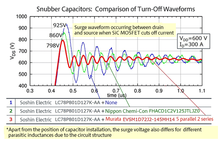
The transistor manufacturers want you to properly snub your circuits. Accordingly, ROHM has a comparison on using film vs ceramic capacitors (Fig. 6). Here they design around the voltage and value limitations of ceramic capacitors by putting two banks of five ceramic capacitors in series. These 10 capacitors give the voltage rating and value commensurate with a single film capacitor.

6. ROHM has experimented with both film and ceramic capacitors for its SiC power transistor snubbers. (Courtesy of ROHM)
Figure 6. ROHM has experimented with both film and ceramic capacitors for its SiC power transistor snubbers. (Courtesy of ROHM)

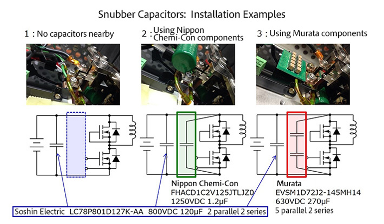
The results achieved by ROHM show how much better the ceramic capacitors damp ringing (Fig. 7). Note that these results are for ROHM’s SiC transistors, which switch very fast and need the optimum snubber network. Also note that the company did not test at the elevated temperatures that power circuits always operate at. It’s your responsibility to ensure that the snubber works well at high temperatures when the ceramic capacitance value drops off.

7. The red trace shows the better attenuation that ceramic capacitors give the ROHM snubber network from Figure 6. (Courtesy of ROHM)
Figure 7. The red trace shows the better attenuation that ceramic capacitors give the ROHM snubber network from Figure 6. (Courtesy of ROHM)

You should also test for acoustic problems from ceramic capacitors. They work as both speakers and microphones. If your converter is operating under 20 kHz, the ceramic snubber capacitors might make objectionable noise. Be sure to find a young person to listen for the noise; anyone over 35 can’t hear above 15 kHz.
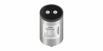
Made for Snubbing

At APEC 2019, TDK promoted its CeraLink capacitors for power conversion. These ceramic capacitors use a lead-lanthanum-zirconium-titanium dielectric (PLZT). This dielectric works in a higher voltage and larger value niche compared to other eramic types (Fig. 8). CeraLink capacitors will increase in capacitance with applied voltage. They do share the same temperature problems as conventional ceramics. TDK notes this might be an advantage since they won’t current hog; that is, the hottest paralleled capacitor will not increase in value and take more current—until it burns up.

8. TDK’s CeraLink capacitors are ceramic capacitors with a unique dielectric. They tend to have a higher value-voltage product. (Courtesy of TDK)
Figure 8. TDK’s CeraLink capacitors are ceramic capacitors with a unique dielectric. They tend to have a higher value-voltage product. (Courtesy of TDK)

This current sharing is critical since the CeraLink capacitors come stacked in an even tighter configuration than conventional stacked MLCC capacitors (Fig. 9). Intended for the dc link capacitor in switching converters, the CeraLink’s high ripple current capacity may also serve in your snubber circuits. TDK’s CeraLink documentation also mentions the physical stresses a voltage pulse will put on a ceramic capacitor. If fast and high enough, it can fracture the capacitor. This is another reason you have to test and measure everything about your snubber design to ensure that it will work at the temperatures and times you need it to.

9. In addition to a special dielectric, TDK’s CeraLink ceramic capacitors come in tightly stacked configurations to lower inductance and equivalent series resistance (ESR). (Courtesy of TDK)
Figure 9. In addition to a special dielectric, TDK’s CeraLink ceramic capacitors come in tightly stacked configurations to lower inductance and equivalent series resistance (ESR). (Courtesy of TDK)

Pick Your Design Method

When I was an auto engineer, it was generally agreed that GM would design things that worked first, and then the company took cost out of the design until it worked well enough. Ford, I can personally attest, designed things cheap, and then added cost until it worked. There’s validity in both methods. I now do all my converter designs on multilayer circuit boards for prototypes. I can take out the cost on a subsequent spin. Alternatively, you might feel best designing in proven film capacitor snubbers, knowing you can add performance and cost with smaller ceramic capacitors.

It’s a tricky decision. The smaller capacitors mean you will have less stray inductance—the very thing that requires larger snubbers. If you can tighten up the entire design, especially with SiC and GaN designs, it might make sense to start with ceramics. Then again, if you need some space to get the heat out of the design, and that space gives room for a film capacitor, well, maybe that’s your best bet. “Maybe” and “analog” go hand-in-hand. Every design and every circuit is unique, as is the situation it’s used in. That’s what makes analog design so challenging, and so rewarding when you get it right.

Source: Electronic Design

Related Posts

Capacitors

Investigating Modeling Techniques of Class II Ceramic Capacitors Losses for High Voltage and Current Applications

15.3.2023
2
Market & Supply Chain

TAIYO YUDEN Announces Completion of MLCC Material Building

15.3.2023
2
Capacitors

Cornell Dubilier Announces Low Inductance DC Link Film Capacitors

14.3.2023
6

Upcoming Events

Mar 15
March 14 @ 12:00 - March 16 @ 14:00 EDT

Design and Test of Non-Hermetic Microelectronic

Mar 19
March 19 - March 23

APEC 2023

Mar 22
14:00 - 15:00 CET

Parasitic Components in Power Converters – Fundamentals and Measurements Rohde & Schwarz Webinar

View Calendar

Popular Posts

  • Ripple Current and its Effects on the Performance of Capacitors

    3 shares
    Share 3 Tweet 0
  • What is a Dielectric Constant of Plastic Materials ?

    4 shares
    Share 4 Tweet 0
  • Understanding High-Precision Resistor Temperature Coefficient of Resistance

    0 shares
    Share 0 Tweet 0
  • Capacitor Selection for Coupling and Decoupling Applications

    28 shares
    Share 28 Tweet 0
  • How to Choose the Right Inductor for DC-DC Buck Applications

    0 shares
    Share 0 Tweet 0
  • Why Low ESR Matters in Capacitor Design

    0 shares
    Share 0 Tweet 0
  • Leakage Current Characteristics of Capacitors

    0 shares
    Share 0 Tweet 0
  • Capacitor Losses (ESR, IMP, DF, Q), Series or Parallel Eq. Circuit ?

    0 shares
    Share 0 Tweet 0

Newsletter Subscription


PCNS Call for Papers !

Archive

2022
2021
2020
2019
2018
2017

Symposium

Passive Components Networking Symposium

Passives e-Learning

Knowledge Blog

  • Home
  • Privacy Policy
  • EPCI Membership & Advertisement
  • About

© EPCI - Premium Passive Components Educational and Information Site

No Result
View All Result
  • Home
  • News
  • Video
  • Knowledge Blog
  • Preferred Suppliers
  • Events

© EPCI - Premium Passive Components Educational and Information Site

Welcome Back!

Login to your account below

Forgotten Password?

Retrieve your password

Please enter your username or email address to reset your password.

Log In
This website uses cookies. By continuing to use this website you are giving consent to cookies being used. Visit our Privacy and Cookie Policy.