• Latest
  • Trending
  • All
  • Capacitors
  • Resistors
  • Inductors
  • Filters
  • Fuses
  • Non-linear Passives
  • Applications
  • Integrated Passives
  • Oscillators
  • Passive Sensors
  • New Technologies
  • Aerospace & Defence
  • Automotive
  • Industrial
  • Market & Supply Chain
  • Medical
  • RF & Microwave
  • Telecommunication

When Benign is Better: Fail Safe Capacitor Technology

28.6.2022

Optimization of 500W LLC Transformer – Case Study

28.3.2023

Flex Suppressor Explained and its Applications

24.3.2023

Exploring the Benefits of High-Performance MLCC Capacitors for Aerospace and Defense

23.3.2023

Murata Establishes Joint Venture Company to Produce MLCC Raw Materials

23.3.2023

Examining the Influence of ESR and Ripple Current on Selecting the Suitable Capacitor

21.3.2023

SABIC Validates its 150°C Film Foil to Enable Adoption of Film Capacitors in SIC Power Modules

20.3.2023
  • Home
  • Privacy Policy
  • EPCI Membership & Advertisement
  • About
No Result
View All Result
NEWSLETTER
Passive Components Blog
  • Home
  • NewsFilter
    • All
    • Aerospace & Defence
    • Antenna
    • Applications
    • Automotive
    • Capacitors
    • Circuit Protection Devices
    • Filters
    • Fuses
    • Inductors
    • Industrial
    • Integrated Passives
    • Market & Supply Chain
    • Medical
    • New Materials & Supply
    • New Technologies
    • Non-linear Passives
    • Oscillators
    • Passive Sensors
    • Resistors
    • RF & Microwave
    • Telecommunication

    Optimization of 500W LLC Transformer – Case Study

    Flex Suppressor Explained and its Applications

    Exploring the Benefits of High-Performance MLCC Capacitors for Aerospace and Defense

    Murata Establishes Joint Venture Company to Produce MLCC Raw Materials

    Examining the Influence of ESR and Ripple Current on Selecting the Suitable Capacitor

    SABIC Validates its 150°C Film Foil to Enable Adoption of Film Capacitors in SIC Power Modules

    Outlook of Passive Electronic Components Market for Oil & Gas Electronics in 2023

    Flying Capacitors Explained

    TDK Introduces Compact High-Current Chokes for Automotive and Industrial Applications

    Trending Tags

    • Ripple Current
    • RF
    • Leakage Current
    • Tantalum vs Ceramic
    • Snubber
    • Low ESR
    • Feedthrough
    • Derating
    • Dielectric Constant
    • New Products
    • Market Reports
  • VideoFilter
    • All
    • Antenna videos
    • Capacitor videos
    • Filter videos
    • Fuse videos
    • Inductor videos
    • Non-linear passives videos
    • Oscillator videos
    • Passive sensors videos
    • Resistor videos
    • Sensors

    Investigating Modeling Techniques of Class II Ceramic Capacitors Losses for High Voltage and Current Applications

    Understanding Basics of Current Sense Resistors

    What Decoupling Capacitor Value To Use And Where To Place Them

    How to Measure Rated Current on Power Inductors

    LTspice Simulation of a Spark-Gap Circuit Protection Surge Arrester

    Approximate Inductor Design Using Two Alternative Cores

    1kW Phase Shift Full Bridge Converter Design and Simulation

    Multiphase Buck Trans-Inductor Voltage Regulator (TLVR) Explained

    Smart Power Distribution Unit Architecture and Inductor Losses

    Trending Tags

    • Capacitors explained
    • Inductors explained
    • Resistors explained
    • Filters explained
    • Application Video Guidelines
    • EMC
    • New Products
    • Ripple Current
    • Simulation
    • Tantalum vs Ceramic
  • Knowledge Blog
  • Suppliers
    • Preferred Suppliers
    • Who is Who
  • Events
No Result
View All Result
Passive Components Blog
No Result
View All Result

When Benign is Better: Fail Safe Capacitor Technology

28.6.2022
Reading Time: 7 mins read
0 0
0
SHARES
2.1k
VIEWS

The performance of a capacitor greatly depends on the environment in which it is used. Exposing a standard capacitor to extreme conditions can cause it to fail, overheat, or even burn. For semi-critical and critical applications, it is necessary to use high reliability components. Fail safe capacitors are designed to withstand harsh conditions, and they are mostly used in applications that demand highly reliable components. Fused tantalum capacitors and open mode multilayer ceramic capacitors (MLCCs) are fail-safe components that are suitable for use in harsh environments.

Fail Safe Multilayer Ceramic Capacitors (MLCCs)

Board flexure can cause both active and passive electronic components to fail. Since multilayer ceramic capacitors (MLCCs) are highly susceptible to mechanical cracking due to their brittle nature, it is necessary for circuit board manufacturers to ensure that their board handling techniques do not expose boards to excessive bending. Some of the processes that can expose boards to excessive bending include mounting in assembling and depanelization. Use of unsupported input/output edge connectors and pick-and-place equipment can also cause excessive bending.

RelatedPosts

Optimization of 500W LLC Transformer – Case Study

Flex Suppressor Explained and its Applications

Exploring the Benefits of High-Performance MLCC Capacitors for Aerospace and Defense

The main causes of mechanical damage to MLCCs can be broadly classified into impact cracking and flex cracking. Impact cracking occurs during the process of placing a component onto a PCB while flex cracking occurs mainly due to excessive board flexure. Although it is possible to minimize board flexure, it is difficult to fully eliminate it. Open mode capacitors are designed to withstand forces that cause mechanical cracks, and they are suitable for applications that demand high-reliability multilayer ceramic capacitors

Open Mode Design MLCCs

Board flexure cracks are a major cause of short circuits and component failure in multilayer ceramic capacitors. Open mode multilayer ceramic capacitors have high tolerance to board flexure cracks, and this makes them a suitable choice for applications that demand protected components. The electrodes of these reduced risk MLCCs are uniquely designed to compensate for the typical crack path caused by excessive PCB bending during manufacturing or assembly.

Excessive bending of a printed circuit board transfers stress to the soldered components. A ceramic capacitor cracks if its breaking strength is less than the applied stress. In some cases, the stress can cause displacement of the component. Such a displacement can cause counter electrodes to come into contact thereby resulting in a short circuit.  The open mode design reduces possibility of a short circuit by reducing the active area in a multilayer ceramic capacitor. Shortening of the electrode layers increases the distance between the counter electrodes and the potential crack. On the flip side, this design compromises the capacitance of a multilayer ceramic capacitor.

Standard MLCCs have no crack protection and they are normally used for non-critical applications. Various designs of MLCCs that have been suggested by manufacturers to decrease the probability of flex cracking can be summarize as following:

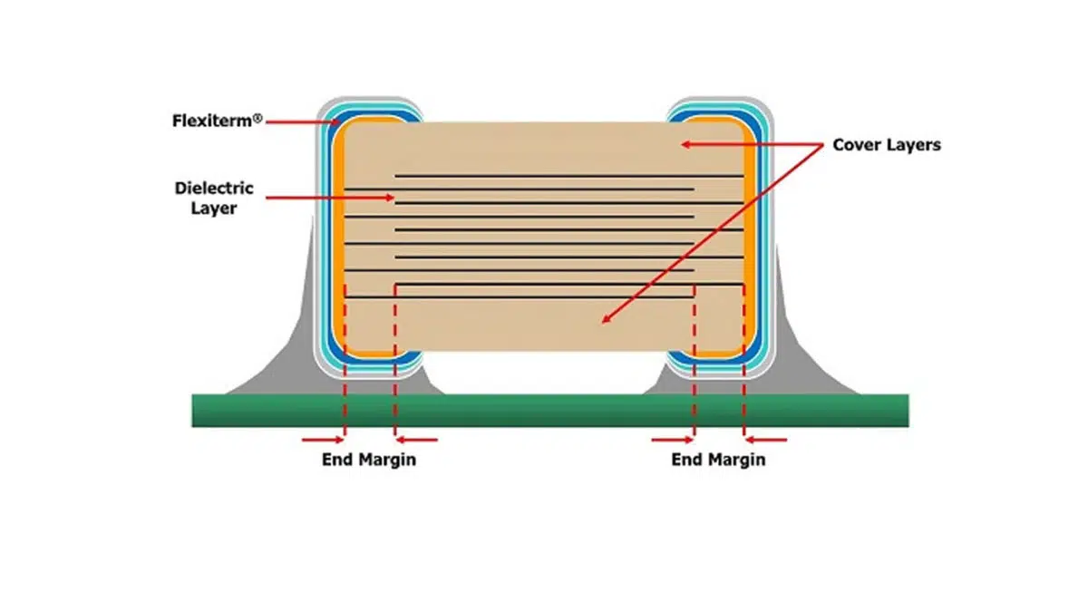
  • Flexible termination. Application of relatively soft and/or tear-away termination layers made of conductive polymers (see featured image and Fig.2.) reduces the stress in ceramic and restricts flex cracks within a safe zone away from the body of the MLCC.
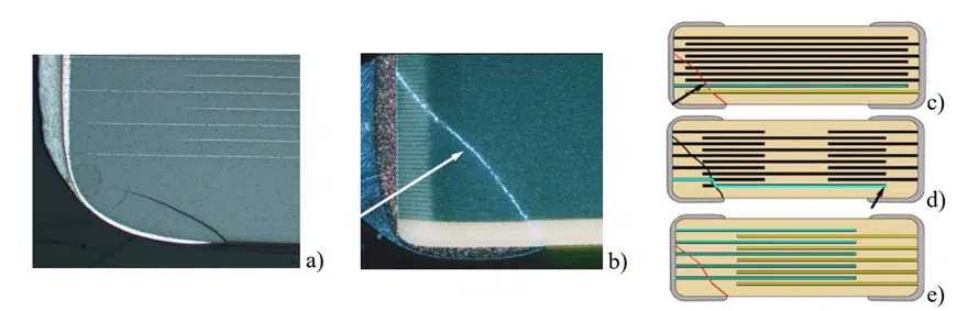
  • Fail open design (Fig.1.e). End margins are widened, so if a crack occurs, it does not cross electrodes with opposite polarity, and thus prevents short-circuit failures.
  • Floating electrodes (Fig. 1.d). Two capacitors connected in series within an individual case size, so the probability of shorting cracks is reduced substantially.
  • Clip-on lead frame. Attachment of J-shaped leads (see Fig. 2) mechanically decouples the MLCC from the PWB and allows for some stress relief.
Fig.1. Cracks in MLCCs and schematics of a standard part – corner “cosmetic” crack out of active zone (a), cross-electrode corner crack (b), standard MLCC design crack (c), floating electrode capacitor (d), and Open Mode design (e). Yellow and blue lines in (c-e) represent electrodes with different polarity; source: Teverovsky NASA

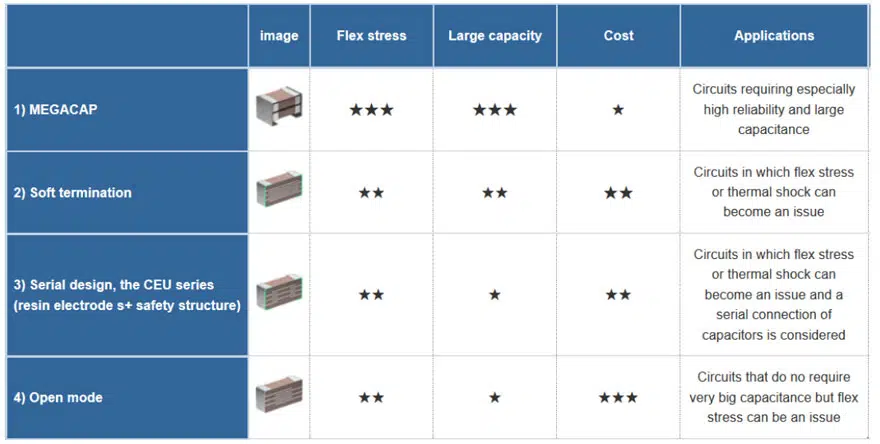
A combination of floating electrode and flex termination design (e.g. a TDK Dual-Fail-Safe, Mega Cap design) allows to reduce the risk of failures even further.
Obviously, the cost of improved reliability of MLCCs with increased margins or floating electrodes is a lesser volumetric efficiency. For this reason, flex termination is likely the most efficient cracking mitigating measure. Typically, capacitors having maximum capacitance values for a given case size and rated voltage have smaller margins and hence, pose a higher risk of failures. For this reason, for a given rated voltage and case size, the use of parts with maximum available value of capacitance at critical applications is not recommended.

Fig.2. MLCC designs with flex crack countermeasures used by TDK

Fail Safe Tantalum Chip Capacitors

The impressive stability and high reliability of solid tantalum capacitors make them a suitable choice for a broad spectrum of applications. They are widely used in circuits that demand components with a long service life and high reliability. In addition, these capacitors are compact in size and have smooth frequency response. Typical high reliability applications of tantalum capacitors include aerospace systems; medical systems such as defibrillators, drug delivery systems, and pacemakers; and filtering circuits. Although tantalum capacitors have high reliability and stability, they are susceptible to high current surges and high voltage. Overstressing solid tantalum capacitors can cause premature failures. Such failures can cause overheating depending on the available energy. Typical conditions that can overstress a tantalum capacitor include thermal overload, inductive transients, excessive voltage, and reverse voltage.

Fused Tantalum Capacitors

Fused or fail-open capacitors are used in circuits where components are likely to be exposed to overstressing; where many capacitors are connected in parallel; or in circuits where capacitors are charged and/or discharged through low impedances. Fail safe tantalum capacitors were widely used in power suppliers and main frame computers. Nevertherless, higher ESR, larger case size and cost increase made this technology obsolete by most manufacturers.

Adding a fuse to a tantalum capacitor helps to enhance its effective reliability. This technology involves adding a fuse element in series with the tantalum capacitor. The capacitor/fuse module switches to high resistance mode, usually above 10MΩ, when the current limit of the fuse is exceeded. The open circuit condition helps to minimize damage to the circuit. Although the high resistance mode can cause detectable performance degradation, it cannot cause a total circuit loss. A fuse element has inherent resistance, and adding it to a tantalum capacitor increases the equivalent series resistance (ESR). This means that the capacitor/fuse assembly has a higher ESR as compared to a standalone capacitor.

Methods of making a capacitor/fuse module

In a capacitor/fuse module, the fuse is placed in such a way that it is in series with the capacitor. Using a fusible link is one of the common methods of making a capacitor/fuse assembly. When excessive current flows through the assembly, it initiates an exothermic reaction that opens the current path. This type of fuse is referred to as electrically activated fuse, and the fusible link is made of two or more metallic elements. Another method of making a fused tantalum capacitor entails using a low melting point wire. The wire melts when excessive current flows though the module. Unlike electrically activated fuses, no exothermic reaction is required to open the thermally activated fuse. Thermal sensitivity, electrical resistances, and speed of operation are some of the key factors that should be considered when manufacturing wire fuses.

Manufacturing a wire fuse involves many manufacturing steps, and the method is not well compatible with most pick-and-place automated assembly equipment. Using ready-made thin-film fuses is, therefore, a better method of producing capacitor/fuse modules. This approach allows better control of the physical and electrical characteristics of the capacitor/fuse assembly, and it is mostly used in the manufacturing of today’s surface mount circuit boards. It yields ultra-miniature assemblies with predictable and precise fusing characteristics. In addition, thin-film construction yields chip-style packages that are easy to mount using modern automated assembly equipment.

The most important ratings to consider when selecting a fuse for a capacitor/fuse module are current interrupt rating and operating voltage rating. The two ratings determine the inrush currents and surges that a fuse can withstand, and exceeding them can cause it to melt or rupture. The current squared seconds (I2t) – a standardized unit that factors the magnitude, duration, and shape of current pulses- is commonly used for categorizing fuses. The I2t of a fuse determines when a fuse will open, and it is one of the key parameters to consider when selecting a fuse for a tantalum capacitor. Apart from voltage rating, current interrupt rating, and I2t values, it is also important to consider pulse de-rating , thermal de-rating, and time-current characteristics when selecting a fuse.

Related Posts

Inductors

Optimization of 500W LLC Transformer – Case Study

28.3.2023
1
Circuit Protection Devices

Flex Suppressor Explained and its Applications

24.3.2023
19
Aerospace & Defence

Exploring the Benefits of High-Performance MLCC Capacitors for Aerospace and Defense

23.3.2023
53

Upcoming Events

Mar 29
15:00 - 16:00 EEST

Supercapacitors vs. Batteries in Engine Starting

Mar 29
17:00 - 18:00 CEST

Practical LLC Transformer Design Methodology

Apr 3
April 3 @ 12:00 - April 4 @ 14:00 CEST

Microelectronic Packaging Failure Modes and Analysis

View Calendar

Popular Posts

  • What is a Dielectric Constant of Plastic Materials ?

    4 shares
    Share 4 Tweet 0
  • Capacitor Selection for Coupling and Decoupling Applications

    28 shares
    Share 28 Tweet 0
  • MLCC and Ceramic Capacitors

    0 shares
    Share 0 Tweet 0
  • Ripple Current and its Effects on the Performance of Capacitors

    3 shares
    Share 3 Tweet 0
  • Why Low ESR Matters in Capacitor Design

    0 shares
    Share 0 Tweet 0
  • Dielectric Constant and its Effects on the Properties of a Capacitor

    7 shares
    Share 7 Tweet 0
  • Leakage Current Characteristics of Capacitors

    0 shares
    Share 0 Tweet 0
  • How to Choose the Right Inductor for DC-DC Buck Applications

    0 shares
    Share 0 Tweet 0

Newsletter Subscription


PCNS Call for Papers !

Archive

2022
2021
2020
2019
2018
2017

Symposium

Passive Components Networking Symposium

Passives e-Learning

Knowledge Blog

  • Home
  • Privacy Policy
  • EPCI Membership & Advertisement
  • About

© EPCI - Premium Passive Components Educational and Information Site

No Result
View All Result
  • Home
  • News
  • Video
  • Knowledge Blog
  • Preferred Suppliers
  • Events

© EPCI - Premium Passive Components Educational and Information Site

Welcome Back!

Login to your account below

Forgotten Password?

Retrieve your password

Please enter your username or email address to reset your password.

Log In
This website uses cookies. By continuing to use this website you are giving consent to cookies being used. Visit our Privacy and Cookie Policy.