Passive Components Blog
No Result
View All Result
  • Home
  • NewsFilter
    • All
    • Aerospace & Defence
    • Antenna
    • Applications
    • Automotive
    • Capacitors
    • Circuit Protection Devices
    • electro-mechanical news
    • Filters
    • Fuses
    • Inductors
    • Industrial
    • Integrated Passives
    • inter-connect news
    • Market & Supply Chain
    • Market Insights
    • Medical
    • Modelling and Simulation
    • New Materials & Supply
    • New Technologies
    • Non-linear Passives
    • Oscillators
    • Passive Sensors News
    • Resistors
    • RF & Microwave
    • Telecommunication
    • Weekly Digest

    Bourns Releases Automotive 1W Flyback Transformer

    Wk 20 Electronics Supply Chain Digest

    Inductor Resonances and its Impact to EMI

    Developing Low Inductance Film Capacitor using Bode 100 Analyzer

    Highly Reliable Flex Rigid PCBs, Würth Elektronik Webinar

    Würth Elektronik Releases High Performance TLVR Coupled Inductors

    YAGEO Extends Rectangular Aluminum Electrolytic Capacitor Family

    Dr. Tomas Zednicek Vision for Europe 2025 Passive Electronics Market

    Littelfuse Releases Industry-First SMD Fuse with 1500A Interrupting Rating at 277V

    Trending Tags

    • Ripple Current
    • RF
    • Leakage Current
    • Tantalum vs Ceramic
    • Snubber
    • Low ESR
    • Feedthrough
    • Derating
    • Dielectric Constant
    • New Products
    • Market Reports
  • VideoFilter
    • All
    • Antenna videos
    • Capacitor videos
    • Circuit Protection Video
    • Filter videos
    • Fuse videos
    • Inductor videos
    • Inter-Connect Video
    • Non-linear passives videos
    • Oscillator videos
    • Passive sensors videos
    • Resistor videos

    Inductor Resonances and its Impact to EMI

    Highly Reliable Flex Rigid PCBs, Würth Elektronik Webinar

    Causes of Oscillations in Flyback Converters

    How to design a 60W Flyback Transformer

    Modeling and Simulation of Leakage Inductance

    Power Inductor Considerations for AI High Power Computing – Vishay Video

    Coupled Inductors in Multiphase Boost Converters

    VPG Demonstrates Precision Resistor in Cryogenic Conditions

    Comparison Testing of Chip Resistor Technologies Under High Vibration

    Trending Tags

    • Capacitors explained
    • Inductors explained
    • Resistors explained
    • Filters explained
    • Application Video Guidelines
    • EMC
    • New Products
    • Ripple Current
    • Simulation
    • Tantalum vs Ceramic
  • Knowledge Blog
  • Suppliers
    • Who is Who
  • Events
No Result
View All Result
Passive Components Blog
No Result
View All Result

When you can not recognize your resistor band code

27.11.2018
Reading Time: 3 mins read
A A

Source: Digikey Tech forum, Reiner Kuehl LinkedIn note, IEC 60062:2016 standard

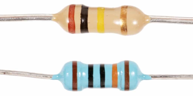
Resistor band code recognition may not be sometimes straightforward as it one could expect. IEC 60062 specifies designation and marking codes for capacitors and resistors. It is latest review 2016 (IEC 60062:2016) includes some significant technical changes with respect to the previous edition such as introduction of the new code colour pink for the coding of the multiplier 10-3. This has not been updated in some reference resource manuals on web. Also sometimes manufacturers have they specific marking style in addition. 

RelatedPosts

Bourns Releases Automotive 1W Flyback Transformer

Wk 20 Electronics Supply Chain Digest

Inductor Resonances and its Impact to EMI

World market of resistors has grown continuously by approx. 5 to 8 % in pieces annually. The total consumption will be probably ahead of 1300 billion pieces in 2018, according to Reiner Kuehl’s estimations.

Further growth can be foreseen. Main reasons are the strong trends to electro-mobility and photovoltaic. These application need special stable resistors in <1 Ohm- and >1 MOhm-ranges, with tight tolerance and low thermal coefficient (TCR). To meet those requirements in the low ohmic range, a new multiplier for the 3rd or 4th color code band ( /1000) has been introduced and added to the standard IEC 60062:2016 its color is PINK.

IEC 60062:2016 specifies designation and marking codes for capacitors and resistors. It provides coding methods for the resistance or capacitance value and its tolerance, including colour coding for resistors. It also provides date code systems suitable for the marking of small components. The latest edition includes the following significant technical changes with respect to the previous edition:

  • introduction of the new code colour pink for the coding of the multiplier 10-3;
  • introduction of new subclauses, 3.2 Prescription of code colours, 3.3 Methods for marking resistance value and tolerance, 3.4 Methods for TCR marking, for improved clarity, the subjects of colour assignment, coding of R value and tolerance, and coding of TCR is dealt with in separate clauses;
  • inclusion of illustrations for TCR marking by interrupted colour band;
  • inclusion of a new subclause on a fixed length code marking, fixed length code marking of resistance values with up to 3 significant digits, hence a fixed code length of 4 digits, and fixed length code marking of capacitance values with up to 2 significant digits, hence a fixed code length of 3 digits;
  • introduction of two new clauses, Clause 6, Coding of properties specific to capacitors and Clause 7, Coding of properties specific to resistors;
  • introduction of Annex A, Special three character coding of resistance value with three significant numerals.

Some troubleshooting in resistor band coding is identified in Digikey Tech forum by Robert Fay:

How do I tell if my resistor is a 4 band or a 5 band? If my 5 band is a 4 band then what is the 5th band?

One key indicator is to look for a gap in the bands. Most resistor companies will put a slightly larger gap between the multiplier and the tolerance gap then between the other bands. Here is an example from Yageo showing a 4 band resistor with a special band.

image


Here is a similar resistor showing a 5 band from Bourns. Though not as pronounced you can see there is a slightly larger gap between the Multiplier and the Tolerance band.

image


Now that you have identified that you have a 4 band resistor with a 5th band you want to know what it is calling out. This can also be a bit tricky.
Per IEC 60062:2016 the standard color code would call out Temp Coefficient.
image

This is not always the case. Yageo for instance uses a Black 5th band in certain series to call out non-inductance.
image

Trying to identify which you have can range from hard to impossible. If it is a color it is most likely a temp coefficient IEC 60062:2016. If your 5th band is black you are best to try to identify the resistor manufacturer and look at their data sheet.

Related

Recent Posts

Inductor Resonances and its Impact to EMI

16.5.2025
20

Causes of Oscillations in Flyback Converters

15.5.2025
18

Vishay Releases Automotive SMD Thick Film Power Resistor for Enhanced Protection Against Short Transient Pulses

14.5.2025
10

How to design a 60W Flyback Transformer

12.5.2025
31

Bourns Extends Rotational Life Option for its Guitar Potentiometer

9.5.2025
6

Modeling and Simulation of Leakage Inductance

9.5.2025
29

Murata and NIMS Built New Database of Dielectric Material Properties

5.5.2025
65

Tariffs Crush Sales Sentiment in April 2025 ECST Results

5.5.2025
85

Shielding Cabinets

29.4.2025
29

Magnetic Shielding and Magnetic Shielding Sheets

29.4.2025
36

Upcoming Events

May 28
16:00 - 17:00 CEST

Power Over Data Line

View Calendar

Popular Posts

  • Buck Converter Design and Calculation

    0 shares
    Share 0 Tweet 0
  • Flyback Converter Design and Calculation

    0 shares
    Share 0 Tweet 0
  • Boost Converter Design and Calculation

    0 shares
    Share 0 Tweet 0
  • Why Low ESR Matters in Capacitor Design

    0 shares
    Share 0 Tweet 0
  • LLC Resonant Converter Design and Calculation

    0 shares
    Share 0 Tweet 0
  • What is a Dielectric Constant and DF of Plastic Materials?

    4 shares
    Share 4 Tweet 0
  • SEPIC Converter Design and Calculation

    0 shares
    Share 0 Tweet 0
  • Ripple Current and its Effects on the Performance of Capacitors

    3 shares
    Share 3 Tweet 0
  • Dual Active Bridge (DAB) Topology Explained

    0 shares
    Share 0 Tweet 0
  • How to Select Ferrite Cores

    0 shares
    Share 0 Tweet 0

Newsletter Subscription


Passive Components Blog

© EPCI - Leading Passive Components Educational and Information Site

  • Home
  • Privacy Policy
  • EPCI Membership & Advertisement
  • About

No Result
View All Result
  • Home
  • Knowledge Blog
  • Premium Suppliers

© EPCI - Leading Passive Components Educational and Information Site

This website uses cookies. By continuing to use this website you are giving consent to cookies being used. Visit our Privacy and Cookie Policy.
Go to mobile version