Passive Components Blog
No Result
View All Result
  • Home
  • NewsFilter
    • All
    • Aerospace & Defence
    • Antenna
    • Applications
    • Automotive
    • Capacitors
    • Circuit Protection Devices
    • electro-mechanical news
    • Filters
    • Fuses
    • Inductors
    • Industrial
    • Integrated Passives
    • inter-connect news
    • Market & Supply Chain
    • Market Insights
    • Medical
    • Modelling and Simulation
    • New Materials & Supply
    • New Technologies
    • Non-linear Passives
    • Oscillators
    • Passive Sensors News
    • Resistors
    • RF & Microwave
    • Telecommunication
    • Weekly Digest

    Samsung Electro-Mechanics High Capacitance MLCCs for ADAS SoCs

    Murata Expands its Automotive Common Mode Choke Coils to 150C and High Current Capability

    Bourns Releases New Current Transformer

    Skeleton Releases GrapheneGPU to Reduce AI Energy Consumption by 44% and Boosts Power by 40%

    VINATech Expands Aluminum Capacitor Portfolio with Acquisition of Enesol

    binder Offers Wide Range of M12 Panel Mount Connectors

    Bourns Releases New Shielded Power Inductors for DDR5

    Supercapacitors Benefits in Industrial Valve Fail-Safe Control Systems

    Wk 21 Electronics Supply Chain Digest

    Trending Tags

    • Ripple Current
    • RF
    • Leakage Current
    • Tantalum vs Ceramic
    • Snubber
    • Low ESR
    • Feedthrough
    • Derating
    • Dielectric Constant
    • New Products
    • Market Reports
  • VideoFilter
    • All
    • Antenna videos
    • Capacitor videos
    • Circuit Protection Video
    • Filter videos
    • Fuse videos
    • Inductor videos
    • Inter-Connect Video
    • Non-linear passives videos
    • Oscillator videos
    • Passive sensors videos
    • Resistor videos

    Coupled Inductors Circuit Model and Examples of its Applications

    Inductor Resonances and its Impact to EMI

    Highly Reliable Flex Rigid PCBs, Würth Elektronik Webinar

    Causes of Oscillations in Flyback Converters

    How to design a 60W Flyback Transformer

    Modeling and Simulation of Leakage Inductance

    Power Inductor Considerations for AI High Power Computing – Vishay Video

    Coupled Inductors in Multiphase Boost Converters

    VPG Demonstrates Precision Resistor in Cryogenic Conditions

    Trending Tags

    • Capacitors explained
    • Inductors explained
    • Resistors explained
    • Filters explained
    • Application Video Guidelines
    • EMC
    • New Products
    • Ripple Current
    • Simulation
    • Tantalum vs Ceramic
  • Knowledge Blog
  • Suppliers
    • Who is Who
  • Events
No Result
View All Result
Passive Components Blog
No Result
View All Result

5G Sub-6 GHz and mmWave Filter Design Considerations Explained

5.1.2022
Reading Time: 5 mins read
A A

Turning 5G wireless communication into a widespread reality will require the use of mmWave frequencies. However, there are many of us RF engineers out there that have spent much of our careers working in the sub-6 GHz range, which actually has quite different needs than mmWave. Therefore, it is critical to get a handle on the key differences between working in this range and mmWave frequencies. Sub-6G and mmWave filter considerations are discussed in article by Peter Matthews, senior technical marketing manager at Knowles Precision Devices published by 5G Technology World.

Three Key Differences Between Sub-6 GHz and mmWave Operations

First and foremost, the rules and specifications, such as those defined by the 3GPP Specification 3GPP TS 38.104 V17.2.0 (2021-06), are different for mmWave. At a high level, this specification defines the frequency ranges where 5G can operate – FR1 (4.1 GHz to 7.125 GHz) and FR2 (24.25 GHz to 52.6 GHz). It also highlights a variety of additional performance requirements that are important to understand when building mmWave base stations and small cells including base station classes, differences in channel bandwidths, and how to test for and handle unwanted emissions.

RelatedPosts

Samsung Electro-Mechanics High Capacitance MLCCs for ADAS SoCs

Murata Expands its Automotive Common Mode Choke Coils to 150C and High Current Capability

Bourns Releases New Current Transformer

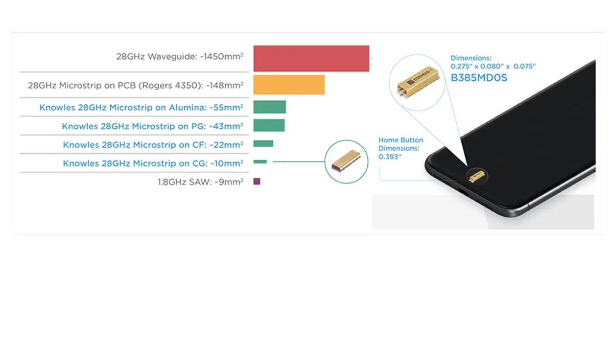
There are also a variety of different RF design challenges at mmWave largely because as frequency increases, wavelength decreases as shown in Figure 1.

Figure 1. Moving operating frequencies from Sub-6GHz to mmWave leads to numerous RF design challenges. Source: Knowles Precision Devices

These challenges include the requirement for small form-factor components that do not sacrifice performance, maintaining dimensional tolerances of antenna and filter technologies, and ensuring temperature stability.

The third big difference between devices operating at sub-6GHz frequencies versus those operating in the mmWave range is the different filtering technologies needed at those frequencies. In general, the lumped-element model does not work well at higher frequencies because manufacturing the necessary discrete values will lead to other issues. Instead, at FR2 frequencies, RF engineers are shifting to a distributed element approach. As a result, transmission line and waveguide-based approaches are the best option.

By developing an understanding of these key differences between FR1 and FR2, making the transition to designing mmWave devices will not seem nearly as daunting.

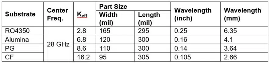
One RF design challenge at these higher frequencies occurs because these designs require small-form-factor components. One of the ways you can achieve this without sacrificing performance is to use high K materials. Table 1 compares the difference in size of a sixth order, half-wave resonator filter built using four different materials.

Table 1. Wavelength and size change as Keff increases. Source: Knowles Precision Devices

Because size is at a premium in mmWave applications, dimensional tolerances of antenna and filter technologies also become critical. Poor tolerance encroaches on system performance. You can avoid this issue by using a fully integrated design featuring thin-film technology and a high-permittivity dielectric. This approach lets you shrink the overall size and reduce variation from board tolerances. Additionally, even though integration of passive functions is not overly difficult at lower frequencies, it can be quite complex at higher frequencies.

Another design issue you’ll encounter in densely packed systems arises because there’s no way to control temperature, which means frequent variations may occur and systems will run hot. Therefore, components such as filters must perform within specification over a wide range of temperatures with a temperature stability of approximately 3 ppm/°C.

Different filter technologies
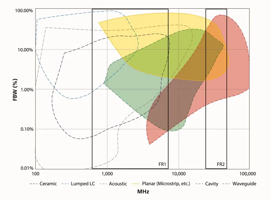
As you move to FR2, you’ll find different radio architectures that include the number and type of filter technologies. Figure 2 shows the typical frequencies and bandwidths of some standard filter technologies and highlights which overlap with the 5G FR1 and FR2 bands.

Figure 2. When moving from FR1 to FR2, certain filter technologies need to be left behind in favor of some of the new types of filters available, shown in color.; source: Knowles Precision Devices

FR2 brings a change from traditional lumped-element filter designs. In general, the lumped-element model does not work well at higher frequencies because manufacturing the necessary discrete values causes other issues. For example, there are board-level parasitic effects that result from mounting components and the transmission lines used in a lumped element model also result in losses. At high frequencies, these effects would essentially detune a filter.

Figure 3. In this microstrip, the upper substrate is air.

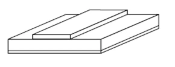
At FR2 frequencies, RF engineers are shifting to using a distributed element model. As a result, transmission lines and waveguides and their corresponding filtering technologies are the best methods for transferring electromagnetic waves around a circuit. More specifically, a microstrip topology is a great option. If you are unfamiliar with microstrip technology, microstrip refers to a type of planar transmission line consisting of a conducting strip separated from a ground plane by a dielectric substrate (Figure 3).

The planar filters used in a microstrip implementation are manufactured using a thin-film process, which offers high Q and a reasonable approach to achieving performance in a small footprint. Planar distributed element filters rely on carefully distributed transmission lines to create resonant structures and can be designed to tighter tolerances than a lumped element filter. This type of planar thin-film implementation is most desirable for mmWave applications from the standpoint of size, cost, and performance.

Making a smooth transition
Even if you’ve been working on RF designs for decades, you should to keep pace with the standards, requirements, and technologies that differ between designing 5G applications that operate sub-6GHz and those at mmWave frequencies.

Instead, to ease this transition, first get to know the 3GPP TS 38.104 V17.2.0 (2021-06) standard. By developing an understanding of these key differences between FR1 and FR2, making the transition to designing mmWave devices will not seem nearly as daunting.

Related

Source: 5G Technology World

Recent Posts

Coupled Inductors Circuit Model and Examples of its Applications

21.5.2025
69

Würth Elektronik Introduces LTspice Models for ESD Products

21.5.2025
45

Littelfuse Gate Driver Integrates Diode and Current Limit Resistor in Compact IC

21.5.2025
21

Capacitor Ripple Current Testing: A Design Consideration

21.5.2025
63

Inductor Resonances and its Impact to EMI

16.5.2025
73

Causes of Oscillations in Flyback Converters

15.5.2025
37

Modelithics Releases Components Library v25.0 for Keysight 

12.5.2025
23

How to design a 60W Flyback Transformer

12.5.2025
63

Murata Releases 008004 High-Frequency SMD Chip Inductor

12.5.2025
31

Modeling and Simulation of Leakage Inductance

9.5.2025
44

Upcoming Events

Jun 4
11:00 - 12:00 CEST

Würth Elektronik PCB Production in Asia

View Calendar

Popular Posts

  • Buck Converter Design and Calculation

    0 shares
    Share 0 Tweet 0
  • Flyback Converter Design and Calculation

    0 shares
    Share 0 Tweet 0
  • Boost Converter Design and Calculation

    0 shares
    Share 0 Tweet 0
  • SEPIC Converter Design and Calculation

    0 shares
    Share 0 Tweet 0
  • Skeleton Releases GrapheneGPU to Reduce AI Energy Consumption by 44% and Boosts Power by 40%

    0 shares
    Share 0 Tweet 0
  • Wk 21 Electronics Supply Chain Digest

    0 shares
    Share 0 Tweet 0
  • Ripple Current and its Effects on the Performance of Capacitors

    3 shares
    Share 3 Tweet 0
  • LLC Resonant Converter Design and Calculation

    0 shares
    Share 0 Tweet 0
  • Flying Capacitors Explained

    0 shares
    Share 0 Tweet 0
  • Why Low ESR Matters in Capacitor Design

    0 shares
    Share 0 Tweet 0

Newsletter Subscription


Passive Components Blog

© EPCI - Leading Passive Components Educational and Information Site

  • Home
  • Privacy Policy
  • EPCI Membership & Advertisement
  • About

No Result
View All Result
  • Home
  • Knowledge Blog
  • Premium Suppliers

© EPCI - Leading Passive Components Educational and Information Site

This website uses cookies. By continuing to use this website you are giving consent to cookies being used. Visit our Privacy and Cookie Policy.
Go to mobile version