Passive Components Blog
No Result
View All Result
  • Home
  • NewsFilter
    • All
    • Aerospace & Defence
    • Antenna
    • Applications
    • Automotive
    • Capacitors
    • Circuit Protection Devices
    • electro-mechanical news
    • Filters
    • Fuses
    • Inductors
    • Industrial
    • Integrated Passives
    • inter-connect news
    • Market & Supply Chain
    • Market Insights
    • Medical
    • Modelling and Simulation
    • New Materials & Supply
    • New Technologies
    • Non-linear Passives
    • Oscillators
    • Passive Sensors News
    • Resistors
    • RF & Microwave
    • Telecommunication
    • Weekly Digest

    H2-Assisted Thermal Treatment of Electrode Materials Increases Supercapacitors Energy Density

    Modelithics Releases Components Library v25.0 for Keysight 

    How to design a 60W Flyback Transformer

    Researchers Present Hybrid Supercapacitor Zn-Ion Microcapacitors

    Murata Releases 008004 High-Frequency SMD Chip Inductor

    Wk 19 Electronics Supply Chain Digest

    Bourns Extends Rotational Life Option for its Guitar Potentiometer

    Modeling and Simulation of Leakage Inductance

    Power Inductor Considerations for AI High Power Computing – Vishay Video

    Trending Tags

    • Ripple Current
    • RF
    • Leakage Current
    • Tantalum vs Ceramic
    • Snubber
    • Low ESR
    • Feedthrough
    • Derating
    • Dielectric Constant
    • New Products
    • Market Reports
  • VideoFilter
    • All
    • Antenna videos
    • Capacitor videos
    • Circuit Protection Video
    • Filter videos
    • Fuse videos
    • Inductor videos
    • Inter-Connect Video
    • Non-linear passives videos
    • Oscillator videos
    • Passive sensors videos
    • Resistor videos

    How to design a 60W Flyback Transformer

    Modeling and Simulation of Leakage Inductance

    Power Inductor Considerations for AI High Power Computing – Vishay Video

    Coupled Inductors in Multiphase Boost Converters

    VPG Demonstrates Precision Resistor in Cryogenic Conditions

    Comparison Testing of Chip Resistor Technologies Under High Vibration

    EMC Challenges for High Speed Signal Immunity and Low EMI

    MOSFET Gate Drive Resistors Power Losses

    Modified Magnetic Reluctance Equivalent Circuit and its Implications

    Trending Tags

    • Capacitors explained
    • Inductors explained
    • Resistors explained
    • Filters explained
    • Application Video Guidelines
    • EMC
    • New Products
    • Ripple Current
    • Simulation
    • Tantalum vs Ceramic
  • Knowledge Blog
  • Suppliers
    • Who is Who
  • Events
No Result
View All Result
Passive Components Blog
No Result
View All Result

Insertion-loss measurements of ferrite absorber sheets

29.7.2019
Reading Time: 8 mins read
A A

Source: EDN blog

by Kenneth Wyatt, president and principal consultant of Wyatt Technical Services.

RelatedPosts

H2-Assisted Thermal Treatment of Electrode Materials Increases Supercapacitors Energy Density

Modelithics Releases Components Library v25.0 for Keysight 

How to design a 60W Flyback Transformer

The development of stealth aircraft brought about the use of ferrite absorber sheets, which have proven useful for damping cavity resonances at microwave frequencies. Since then, ferrite absorber sheets have become useful at mitigating EMI. Most absorber sheets act as magnetic shields that help “redirect” magnetic fields and become effective at gigahertz frequencies. As my measurements show, some are effective even at much lower frequencies, serving as shielding or absorbers for high-frequency EMI from clock harmonics in the hundreds of megahertz.
I’ve used these absorbers for my EMC clients to help shield or absorb harmonic energy in the GHz frequencies. One client had transmitter high-order harmonics well into the gigahertz band and I found the absorber, when placed under the circuit board, reduced the harmonics by 8 dB to 14 dB between 2 GHz to 6 GHz. More often, however, I need something effective in the LTE cellular frequency range of 700 MHz to 900 MHz and it seems few absorber materials are very effective in this range. I needed a quick way to characterize the many absorber materials I had at hand.

Unfortunately, manufacturers of these materials rarely show the absorptive properties versus frequency, but rather the permeability curves. While higher permeability materials usually mean better shielding at lower frequencies, EMC engineers are more interested in specific absorption (in dB) versus frequency, such information makes it easier to specify the correct material, depending on the application. I’ve made these measurements and present my results here. Figure 1 shows the tested samples.


Figure 1. Measurements for insertion loss covered a variety of ferrite absorber sheets. Photo by Kenneth Wyatt.

Würth Elektronik has a useful application note, ANP022, “Selection and Characteristics of WE-FSFS (Flexible Sintered Ferrite Sheet)” that shows a simple measurement technique for determining the insertion loss versus frequency. Using this technique, I was able to test the samples in less than one hour.

The overall test setup was simple, requiring only a spectrum analyzer with tracking generator (Siglent SSA3032X) and a 50-Ω microstrip transmission line (Figure 2).


Figure 2
. The test setup showing the spectrum analyzer and tracking generator connected to each end of the 50-Ω transmission line. Photo by Kenneth Wyatt.

Once the transmission line is normalized, we merely place and hold the sample absorber on top of the microstrip. Generally, I measured from 100 MHz to 3.2 GHz (the upper limit of my analyzer). I always made sure there was the tear-off plastic strip against the microstrip, rather than the raw ferrite. See Figure 3.


Figure 3
. Example of an absorber measurement. Each sample was simply held down against the microstrip. Photo by Kenneth Wyatt.

Placing the absorber on top of the microstrip will absorb an increasing amount of magnetic flux as frequency is increased. This will be indicated by the increase in insertion loss in the display. I suspect the loss will increase as the sample size is increased, but didn’t explore that aspect in detail.

Samples were tested from 3M, Arc-Tech, Chomerics, NEC/Tokin, and Würth Elektronik. Specific part numbers are within the captions below. Listed in alphabetical order. Figure 4 covers 3M while figures 5, 6, and 7 show results for Arc-Tech. Page 2 covers materials from Parker Chomerics, NEC, and Würth Elektronik.


Figure 4. Insertion loss for 3M P/N CN-3190 (yellow) and AB50105 (violet). Sample size: 7.5×8 cm and 10.5×14.5 cm, respectively.


Figure 5. Arc-Tech’s WAVE-X P/N LS10055 (yellow). Sample size: 15×15 cm.


Figure 6. Arc-Tech’s WAVE-X P/N SB1007040 (yellow) and SB1007020 (violet). Sample size: 15×15 cm.


Figure 7. Arc-Tech’s WAVE-X P/N WXA10 (yellow) and WXA20 (violet). Sample size: 15×15 cm.

The Arc-Tech WX-A series had excellent insertion loss of 10 to 40 dB above 1 GHz and should prove useful for applications in the cellular, GPS, and 2.4 GHz Wi-Fi bands.


Figure 8. Parker Chomerics P/N SS4850-0100 (yellow), SS4850-0150 (violet), and SS4850-0300 (blue). Sample size: 6.5×13 cm, 12×13 cm, and 12×13 cm, respectively.

The Chomerics material is unique in that it has substantial absorption properties starting around 20 MHz and increasing to 20 dB insertion loss above 1 GHz. As you can see, I had to greatly expand the frequency span to capture the whole picture.

Figure 9 and Figure 10 look at products from NEC.


Figure 9. NEC P/N EFR(01) (yellow), FK2(03) (violet), and R4N(01) (blue). Sample size: all 8×8 cm.


Figure 10. NEC P/N R4N(04) (yellow), and K4E(05) (violet). Sample size: all 8×8 cm.

Generally, materials from Würth Elektronik are more effective in the higher gigahertz frequency bands. See Figure 11 for an example frequency plot from the company’s application note.


Figure 11. Insertion loss versus frequency for the typical Würth Elektronik “WE-FSFS” samples. Figure courtesy of Würth Elektronik.

Note that this set of curves extends out to 6 GHz, but yields just a nominal 3 dB to 9 dB insertion loss at that extreme. This is actually pretty typical for most of the absorber material I measured, where they are most useful in the higher GHz frequencies.


Figure 12. Würth Elektronik P/N 354001 (yellow), 354002 (violet), and 354003 (blue). Sample size: all 12 x 12 cm. These are approaching 8 to 10 dB insertion loss at 3 GHz.


Figure 13. Würth Elektronik P/N 354004 (yellow), 354005 (violet), and 354006 (blue). Sample size: all 6×6 cm.


Figure 14. Würth Elektronik P/N 364001 (yellow), 364002 (violet), and 364003 (blue). Sample size: all 12×12 cm. These are approaching 6 dB to 8 dB insertion loss at 3 GHz.


Figure 15. Würth Elektronik P/N 364004 (yellow), 364005 (violet), and 364006 (blue). Sample size: all 6×6 cm.


I hope this information is useful to you as you’re designing smaller wireless products, where every bit of shielding and attenuation of self-generated EMI is important. Würth Elektronik described some alternative ways of characterizing ferrite absorber sheets, but the microstrip method was quick and easy.
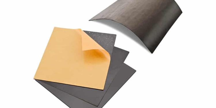
Featured image: Sintered flexible ferrite magnetic shields, credit Würth Elektronik
References

  1. Würth Elektronik Applications Note ANP022, Selection and Characteristics of WE-FSFS
  2. Würth Elektronik, Trilogy of Magnetics (5th Edition)
  3. IoT: The Interference of Things, Martin Rowe, EDN
  4. Platform interference, Kenneth Wyatt, EDN

Related

Recent Posts

How to design a 60W Flyback Transformer

12.5.2025
10

Murata Releases 008004 High-Frequency SMD Chip Inductor

12.5.2025
8

Modeling and Simulation of Leakage Inductance

9.5.2025
10

Power Inductor Considerations for AI High Power Computing – Vishay Video

9.5.2025
18

TAIYO YUDEN Releases Compact SMD Power Inductors for Automotive Application

9.5.2025
12

YAGEO Releases High Current SMD Common Mode Choke With Shape Core Construction

5.5.2025
25

Tariffs Crush Sales Sentiment in April 2025 ECST Results

5.5.2025
71

Würth Elektronik Offers New Power Supplies Development Kit

29.4.2025
37

Bourns Extends Shielded Power Inductors by Four New Series

29.4.2025
18

Bourns Unveils Automotive 1kV BMS Signal Transformer

25.4.2025
12

Upcoming Events

May 14
11:00 - 12:00 CEST

Reliable RIGID.flex PCBs for Critical Applications – Made in Europe

May 14
17:00 - 17:30 CEST

Calculating Foil Winding Losses with AI

May 28
16:00 - 17:00 CEST

Power Over Data Line

View Calendar

Popular Posts

  • Buck Converter Design and Calculation

    0 shares
    Share 0 Tweet 0
  • Boost Converter Design and Calculation

    0 shares
    Share 0 Tweet 0
  • SEPIC Converter Design and Calculation

    0 shares
    Share 0 Tweet 0
  • What is a Dielectric Constant and DF of Plastic Materials?

    4 shares
    Share 4 Tweet 0
  • Flyback Converter Design and Calculation

    0 shares
    Share 0 Tweet 0
  • Flying Capacitors Explained

    0 shares
    Share 0 Tweet 0
  • LLC Resonant Converter Design and Calculation

    0 shares
    Share 0 Tweet 0
  • Dual Active Bridge (DAB) Topology Explained

    0 shares
    Share 0 Tweet 0
  • Supercapacitors Emerge as a Promising Solution to AI-Induced Power Energy Spikes

    0 shares
    Share 0 Tweet 0
  • MLCC and Ceramic Capacitors

    0 shares
    Share 0 Tweet 0

Newsletter Subscription


Passive Components Blog

© EPCI - Leading Passive Components Educational and Information Site

  • Home
  • Privacy Policy
  • EPCI Membership & Advertisement
  • About

No Result
View All Result
  • Home
  • Knowledge Blog
  • Premium Suppliers

© EPCI - Leading Passive Components Educational and Information Site

This website uses cookies. By continuing to use this website you are giving consent to cookies being used. Visit our Privacy and Cookie Policy.
Go to mobile version