Passive Components Blog
No Result
View All Result
  • Home
  • NewsFilter
    • All
    • Aerospace & Defence
    • Antenna
    • Applications
    • Automotive
    • Capacitors
    • Circuit Protection Devices
    • electro-mechanical news
    • Filters
    • Fuses
    • Inductors
    • Industrial
    • Integrated Passives
    • inter-connect news
    • Market & Supply Chain
    • Market Insights
    • Medical
    • Modelling and Simulation
    • New Materials & Supply
    • New Technologies
    • Non-linear Passives
    • Oscillators
    • Passive Sensors News
    • Resistors
    • RF & Microwave
    • Telecommunication
    • Weekly Digest

    Bourns Extends Rotational Life Option for its Guitar Potentiometer

    Modeling and Simulation of Leakage Inductance

    Power Inductor Considerations for AI High Power Computing – Vishay Video

    TAIYO YUDEN Releases Compact SMD Power Inductors for Automotive Application

    Fischer Releases High Vibration Robust Ratchet Locking USB-C Connector System

    Littelfuse Unveils High-Use Tactile Switches with 2 Million Cycle Lifespan

    KYOCERA AVX Releases Compact High-Directivity Couplers

    Supercapacitors Emerge as a Promising Solution to AI-Induced Power Energy Spikes

    Wk 18 Electronics Supply Chain Digest

    Trending Tags

    • Ripple Current
    • RF
    • Leakage Current
    • Tantalum vs Ceramic
    • Snubber
    • Low ESR
    • Feedthrough
    • Derating
    • Dielectric Constant
    • New Products
    • Market Reports
  • VideoFilter
    • All
    • Antenna videos
    • Capacitor videos
    • Circuit Protection Video
    • Filter videos
    • Fuse videos
    • Inductor videos
    • Inter-Connect Video
    • Non-linear passives videos
    • Oscillator videos
    • Passive sensors videos
    • Resistor videos

    Modeling and Simulation of Leakage Inductance

    Power Inductor Considerations for AI High Power Computing – Vishay Video

    Coupled Inductors in Multiphase Boost Converters

    VPG Demonstrates Precision Resistor in Cryogenic Conditions

    Comparison Testing of Chip Resistor Technologies Under High Vibration

    EMC Challenges for High Speed Signal Immunity and Low EMI

    MOSFET Gate Drive Resistors Power Losses

    Modified Magnetic Reluctance Equivalent Circuit and its Implications

    Improving Common Mode Noise Reduction while Decreasing BOM

    Trending Tags

    • Capacitors explained
    • Inductors explained
    • Resistors explained
    • Filters explained
    • Application Video Guidelines
    • EMC
    • New Products
    • Ripple Current
    • Simulation
    • Tantalum vs Ceramic
  • Knowledge Blog
  • Suppliers
    • Who is Who
  • Events
No Result
View All Result
Passive Components Blog
No Result
View All Result

Calculating for KVA in Single and Three Phase Transformers

4.4.2018
Reading Time: 2 mins read
A A

Source: Sensors online article

by Andrew Holland |Apr 3, 2018 1:37pm. Need to size a single or three-phase transformer? Transformer sizes are dictated by their respective KVA rating. Using common variables, one can compute for the required KVA rating or transformer size for a particular project, system or operation. This article provides basic formulas for finding the correct size of single and three-phase transformers using load voltage and load current.

RelatedPosts

Bourns Extends Rotational Life Option for its Guitar Potentiometer

Modeling and Simulation of Leakage Inductance

Power Inductor Considerations for AI High Power Computing – Vishay Video

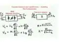
Single Phase KVA Calculation

The formula for finding the required KVA or transformer size for single-phase power is the following:

Volts x Amps / 1,000 = KVA

Based on the equation, one would need to plug in the proper load/output (secondary) voltage and current (amps) to compute for KVA. Note that load voltage is not the same as line voltage, which is also known as primary voltage or input.

Example: Find the KVA or transformer size for load voltage of 120V 1PH and a load current of 50A.

120 x 50 / 1,000 = KVA

6,000 / 1,000 = KVA

= 6 KVA


Three-phase KVA Calculation

Businesses that require three-phase power need to add an extra component in the formula to arrive at the correct transformer size, i.e., square root of 3 (√3) or 1.732. This figure is a constant found in three phase, as the phases do not generate the same amount of power (simultaneously). Furthermore, three-phase transformers handle three lines of AC power, with each of the three lines 120 degrees out of phase from the other two lines.

With this in mind, the new formula can be found below:

Volts x Amps x √3 / 1,000 = KVA

Example: Find the KVA or transformer size for load voltage of 240 3PH and a load current of 60 amps.

240 x 60 x 1.732 / 1,000 = KVA

= 24.94 KVA (or 25 KVA after rounding up)


Future Expansion and Standard Transformer Sizes

Computing for the required KVA is not the final step in determining the proper transformer size. Most computations (especially for three-phase loads) do not provide a whole number. As a result, the value must be rounded up, as seen in the sample above. It is best practice to always round up and not down.

Next, in order to factor in future expansion and prevent risks associated with accidental overloading, one should add 20 percent of spare capacity. Taking the three-phase sample again, we simply add 20 percent to the rounded figure:

25 KVA + 5 = 30 KVA

Lastly, one may find that the specific transformer size needed is not being offered or is unavailable by the store or preferred manufacturer. In most cases, this is because there are standard KVA sizes for transformers. If you cannot find the size you need, simply round up again to the next standard KVA size.

For referencing, the standard KVA sizes for singe-phase transformers are 1, 1.5, 2, 3, 5, 7.5, 10, 15, 25, 37.5, 50, 75, 100, 167, 200, 250 and 333 KVA

Taking our answer from the single-phase example above – 6 KVA or 7.2 KVA (with 20% spare capacity); we can see that there is no standard single-phase equivalent available. As a solution, simply round up to the next standard single-phase KVA size: 7.5 KVA.

Standard sizes for three-phase transformers are 3, 6, 9, 15, 30, 45, 75, 112.5, 150, 225, 300, 500, 750 and 1,000 KVA

Taking our final three-phase figure of 30 KVA, we can see that it matches with a standard three-phase transformer size above, i.e., 30 KVA. No further rounding or conversion is needed, since 30 KVA is a standard three-phase transformer size.

Related

Recent Posts

Modeling and Simulation of Leakage Inductance

9.5.2025
2

Murata and NIMS Built New Database of Dielectric Material Properties

5.5.2025
49

Hybrid Electrochemical Electrolytic Capacitor Provides High Frequency and High Capacitance Performance

25.4.2025
47

RF Inductors Key Characteristics and Applications

17.4.2025
56

Coupled Inductors in Multiphase Boost Converters

11.4.2025
81

Enhanced Process Control in Tantalum Capacitor Anode Manufacturing Reduces Cost and Improves Reliability

8.4.2025
20

The Path to Thinner MLCCs and Innovative Capacitor Development

2.4.2025
177

Impact of Channel Length of the Pores to Supercapacitor Performance 

24.3.2025
25

Enhancing Effectiveness of Tantalum Capacitor Anode Control

23.3.2025
29

Supercapacitor Separator with High Ionic Conductivity Enables Line-Filter Applications at High Power

21.3.2025
46

Upcoming Events

May 14
11:00 - 12:00 CEST

Reliable RIGID.flex PCBs for Critical Applications – Made in Europe

May 14
17:00 - 17:30 CEST

Calculating Foil Winding Losses with AI

May 28
16:00 - 17:00 CEST

Power Over Data Line

View Calendar

Popular Posts

  • Buck Converter Design and Calculation

    0 shares
    Share 0 Tweet 0
  • Boost Converter Design and Calculation

    0 shares
    Share 0 Tweet 0
  • Flyback Converter Design and Calculation

    0 shares
    Share 0 Tweet 0
  • Flying Capacitors Explained

    0 shares
    Share 0 Tweet 0
  • What Electronics Engineer Needs to Know About Passive Low Pass Filters

    0 shares
    Share 0 Tweet 0
  • Ripple Current and its Effects on the Performance of Capacitors

    3 shares
    Share 3 Tweet 0
  • SEPIC Converter Design and Calculation

    0 shares
    Share 0 Tweet 0
  • Filter Q Factor Explained

    0 shares
    Share 0 Tweet 0
  • Supercapacitors Emerge as a Promising Solution to AI-Induced Power Energy Spikes

    0 shares
    Share 0 Tweet 0
  • Dual Active Bridge (DAB) Topology Explained

    0 shares
    Share 0 Tweet 0

Newsletter Subscription


Passive Components Blog

© EPCI - Leading Passive Components Educational and Information Site

  • Home
  • Privacy Policy
  • EPCI Membership & Advertisement
  • About

No Result
View All Result
  • Home
  • Knowledge Blog
  • Premium Suppliers

© EPCI - Leading Passive Components Educational and Information Site

This website uses cookies. By continuing to use this website you are giving consent to cookies being used. Visit our Privacy and Cookie Policy.
Go to mobile version