Passive Components Blog
No Result
View All Result
  • Home
  • NewsFilter
    • All
    • Aerospace & Defence
    • Antenna
    • Applications
    • Automotive
    • Capacitors
    • Circuit Protection Devices
    • electro-mechanical news
    • Filters
    • Fuses
    • Inductors
    • Industrial
    • Integrated Passives
    • inter-connect news
    • Market & Supply Chain
    • Market Insights
    • Medical
    • Modelling and Simulation
    • New Materials & Supply
    • New Technologies
    • Non-linear Passives
    • Oscillators
    • Passive Sensors News
    • Resistors
    • RF & Microwave
    • Telecommunication
    • Weekly Digest

    YAGEO Offers High-Performance Diplexers for Dual-Band Wi-Fi 6E/7Integration

    European Components Distribution (DMASS) Faces Continued Decline in Q2 2025

    TDK Announced Wide Frequency Automotive Wirewound POC Inductors

    Bourns Released Rugged, High-Power TO-247 Thick Film Resistor

    Bourns Announced Shielded Power Inductor with High Saturation and Low Radiation

    Würth Elektronik Expands MagI³C with Variable Step-Down Modules

    KYOCERA AVX Releases 600MHz Band71 Compact SAW Duplexer

    binder Supports Miniaturization of Power Supplies with M12 Compact Connectors

    Switched Capacitor Converter Explained

    Trending Tags

    • Ripple Current
    • RF
    • Leakage Current
    • Tantalum vs Ceramic
    • Snubber
    • Low ESR
    • Feedthrough
    • Derating
    • Dielectric Constant
    • New Products
    • Market Reports
  • VideoFilter
    • All
    • Antenna videos
    • Capacitor videos
    • Circuit Protection Video
    • Filter videos
    • Fuse videos
    • Inductor videos
    • Inter-Connect Video
    • Non-linear passives videos
    • Oscillator videos
    • Passive sensors videos
    • Resistor videos

    Switched Capacitor Converter Explained

    Understanding Inductor Dot Markings and Their Application in LTspice

    Accelerating Full Bridge LLC Resonant Converter Design with Frenetic AI

    Understanding Switched Capacitor Converters

    Coupled Inductors Circuit Model and Examples of its Applications

    Inductor Resonances and its Impact to EMI

    Highly Reliable Flex Rigid PCBs, Würth Elektronik Webinar

    Causes of Oscillations in Flyback Converters

    How to design a 60W Flyback Transformer

    Trending Tags

    • Capacitors explained
    • Inductors explained
    • Resistors explained
    • Filters explained
    • Application Video Guidelines
    • EMC
    • New Products
    • Ripple Current
    • Simulation
    • Tantalum vs Ceramic
  • Knowledge Blog
  • Suppliers
    • Who is Who
  • Events
No Result
View All Result
Passive Components Blog
No Result
View All Result

A Versatile RLC-Box for the Electronics Lab or Schools

14.3.2019
Reading Time: 3 mins read
A A

Source: Kickstarter project

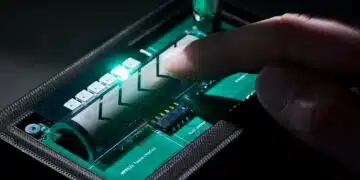
Electronic enthusiasts may be interested in a new versatile RLC-Box created by electronics hobbyist Roger Leifert based in Aachen, Germany. The project is kicked by Kickstarter, early bird pledges are available from €199 with worldwide shipping expected to take place during July 2019.

RelatedPosts

YAGEO Offers High-Performance Diplexers for Dual-Band Wi-Fi 6E/7Integration

European Components Distribution (DMASS) Faces Continued Decline in Q2 2025

TDK Announced Wide Frequency Automotive Wirewound POC Inductors

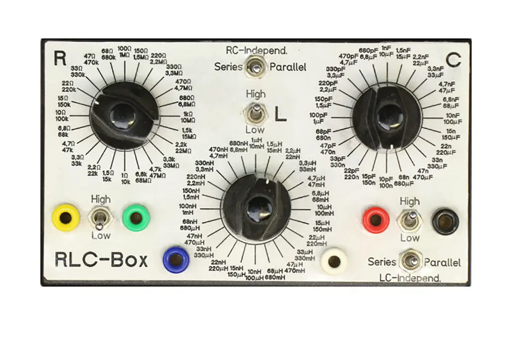
Dial in any value from 8 Decades Resistors, Capacitors & Inductors. R, L, C isolated or any possible RC, LC, RL, RLC combinations.

When developing electronics or doing repair-/restoration work you often need to find the right value of a resistor, capacitor or inductor or any series- or parallel-combination of them e.g. when finding the right values for a low-pass filter.

Instead of soldering together dozens of possible combinations or building it up on a breadboard, searching your parts bins for unavailable values etc. here you have one device that does it all.

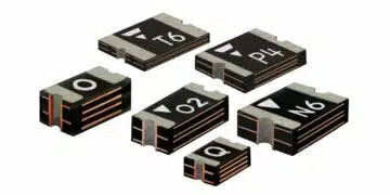
With 3 rotary-switches you can select from 8 decades of values (E6-Series, roughly 50% increase per step; inductors only 7 decades).The rotary switches have 24 positions and 2 planes (“Upper”/”Lower”) that gives you a selection of 48 values. The resistors have a range from 1 Ohm to 100 Megohms and are 1206-SMD type with 1% accuracy (5% above 10 Megohms) and 0.5Watt power-rating.

The capacitors have a range from 10 pF to 1,000 µF. They are 1206-SMD NP0/COG ceramic-types (5%) from 10 pF to 68nF, then polypropylene 5% film-capacitors up to 680nF, then 5% standard film capacitors up to 68µF and above that electrolytic capacitors (20%). All capacitors have at least 50VDC/35VAC-rating and are low-loss/high-quality types to give the best performance also at higher frequencies.

The inductors have a range from 10nH up to 150mH. They are all ferrite-type inductors from reputable manufacturer FASTRON. Wherever possible we choose a type with >1A current capability, DC-resistance below 1 Ohm and 5% accuracy. The desirend current and resistance rating only holds up about the 100µH types. Above that you don´t get low-resistance/high-current inductors in form-factors suitable for the RLC-box.

All component-types with their characteristics and ratings will be listed in the manual. But the highlight is to connect the 3 indepent types of components in any useful combination of 2 or 3 in series and/or in parallel. 2 switches with 6 binding-posts make it possibe to quickly change not only the values but by switching the neighbouring component in series or in parallel to it.

That way you can get low-pass, high-pass, band-pass, band-stop, RLC series-tank circuits and RLC parallel tank-circuits. Low-pass and high-pass filters can be build with 6dB falloff per octave (=20dB/decade) with an RC-filter or 12dB/octave (=40dB/decade) falloff with an RLC-filter.

The necessary switch settings and connection diagram as well as the characteristics (-3dB corner-frequency) and circuit diagran for each of the above circuits will be detailed in the manual. Because the RLC-Box consists of purely passive components there is no EMI-emission, but the box is susceptible to strong electromagnetic fields due to the unshielded plastic case. Nevertheless I took all measures to make the RLC-Box also useable for RF-applications by minimizing parasitic inductances and capacitances. Those properties can only be determined in the finished product.

The general rating for the RLC-Box is max. 50VDC/35VAC and max. 150mA (rotary switch-current rating). The positive terminal (“anode”) of the electrolytic capacitors is marked by the red binding post, the negative terminal (“cathode”) by the black binding post. When using one of the electrolytic capacitors in the RLC-Box watch out for applying only positive voltages (“DC”) with the correct polarity or a mixed AC+DC-waveform where the lowest voltage in the waveform is still positive.

The RLC-box is easily repairable. All circuit-diagrams, component-values and characteristics and the design-files will be published after a successful run of the campaign under the Open Source Hardware license.

Related

Recent Posts

European Components Distribution (DMASS) Faces Continued Decline in Q2 2025

30.7.2025
2

TDK Announced Wide Frequency Automotive Wirewound POC Inductors

30.7.2025
1

Bourns Released Rugged, High-Power TO-247 Thick Film Resistor

30.7.2025
1

Bourns Announced Shielded Power Inductor with High Saturation and Low Radiation

30.7.2025
1

Würth Elektronik Expands MagI³C with Variable Step-Down Modules

30.7.2025
2

Switched Capacitor Converter Explained

28.7.2025
7

Samsung Releases 1000V 1812 X7R 100nF MLCC for Electric Vehicles

28.7.2025
15

Samsung Electro-Mechanics Releases Molded MLCC Capacitors

28.7.2025
19

Researchers Demonstrated 200C Polymer Film Dielectric

28.7.2025
10

Researchers Demonstrated Zinc-Ion Based Photo-Supercapacitor

28.7.2025
9

Upcoming Events

Jul 30
19:00 - 19:30 CEST

Dimension constrains in 500W PSFB Transformer Design

Sep 22
September 22 @ 13:00 - September 25 @ 15:15 EDT

Pre Cap Visual Inspection per Mil-Std-883 (TM 2017)

Sep 30
September 30 @ 12:00 - October 2 @ 14:00 EDT

MIL-Std-883 TM 2010

Oct 17
12:00 - 14:00 EDT

External Visual Inspection per MIL-STD-883 TM 2009

Oct 21
October 21 @ 12:00 - October 23 @ 14:15 EDT

Space and Military Standards for Hybrids and RF Microwave Modules

View Calendar

Popular Posts

  • Buck Converter Design and Calculation

    0 shares
    Share 0 Tweet 0
  • Boost Converter Design and Calculation

    0 shares
    Share 0 Tweet 0
  • Flyback Converter Design and Calculation

    0 shares
    Share 0 Tweet 0
  • LLC Resonant Converter Design and Calculation

    0 shares
    Share 0 Tweet 0
  • What is a Dielectric Constant and DF of Plastic Materials?

    4 shares
    Share 4 Tweet 0
  • Ripple Current and its Effects on the Performance of Capacitors

    3 shares
    Share 3 Tweet 0
  • Dual Active Bridge (DAB) Topology Explained

    0 shares
    Share 0 Tweet 0
  • How to Design an Inductor

    0 shares
    Share 0 Tweet 0
  • MLCC Case Sizes Standards Explained

    0 shares
    Share 0 Tweet 0
  • MLCC and Ceramic Capacitors

    0 shares
    Share 0 Tweet 0

Newsletter Subscription


Passive Components Blog

© EPCI - Leading Passive Components Educational and Information Site

  • Home
  • Privacy Policy
  • EPCI Membership & Advertisement
  • About

No Result
View All Result
  • Home
  • Knowledge Blog
  • Premium Suppliers

© EPCI - Leading Passive Components Educational and Information Site

This website uses cookies. By continuing to use this website you are giving consent to cookies being used. Visit our Privacy and Cookie Policy.
Go to mobile version