Passive Components Blog
No Result
View All Result
  • Home
  • NewsFilter
    • All
    • Aerospace & Defence
    • Antenna
    • Applications
    • Automotive
    • Capacitors
    • Circuit Protection Devices
    • electro-mechanical news
    • Filters
    • Fuses
    • Inductors
    • Industrial
    • Integrated Passives
    • inter-connect news
    • Market & Supply Chain
    • Market Insights
    • Medical
    • Modelling and Simulation
    • New Materials & Supply
    • New Technologies
    • Non-linear Passives
    • Oscillators
    • Passive Sensors News
    • Resistors
    • RF & Microwave
    • Telecommunication
    • Weekly Digest

    Vishay Introduces SMD Polymer PTC Thermistors for Fast Resettable Overcurrent Protection

    MLCCs in the Age of AI: Q2 2026 Market Tightness

    AI Hardware Demand for Passive Components Dossier

    June 2026 Interconnect, Passives and Electromechanical Components Market Insights

    KYOCERA AVX Presents Antenna Integrator Studio Tutorial for Antenna Placement and RF Design

    Power Design Simulation Tools for Faster Inductor Selection and Loss Optimization

    Wk 25 Electronics Supply Chain Digest

    Skeleton Supercapacitor Achieves UL‑certified 3,500 A Peak Current for AI Data Centers

    Bourns Planar Transformers for SiC and GaN Gate Driver Isolation

    Trending Tags

    • Ripple Current
    • RF
    • Leakage Current
    • Tantalum vs Ceramic
    • Snubber
    • Low ESR
    • Feedthrough
    • Derating
    • Dielectric Constant
    • New Products
    • Market Reports
  • VideoFilter
    • All
    • Antenna videos
    • Capacitor videos
    • Circuit Protection Video
    • Filter videos
    • Fuse videos
    • Inductor videos
    • Inter-Connect Video
    • Non-linear passives videos
    • Oscillator videos
    • Passive sensors videos
    • Resistor videos

    KYOCERA AVX Presents Antenna Integrator Studio Tutorial for Antenna Placement and RF Design

    Power Design Simulation Tools for Faster Inductor Selection and Loss Optimization

    EMC‑Compliant PCB and Connector Design Guidelines

    Why Isolated DC/DC Power Supplies Fail Late, Würth Elektronik Podcast

    Designing 800 V DC EMC Filters: Calculation, Simulation and Measurement

    Current Sense Transformer Datasheet and Design‑in Guide

    Designing a USB Type‑C Flyback Planar Transformer with Frenetic’s Planar Tool

    Magnetics Design in High‑Frequency GaN Converters

    Qi2 Wireless Charging: Inductors, Capacitors and EMC Filters

    Trending Tags

    • Capacitors explained
    • Inductors explained
    • Resistors explained
    • Filters explained
    • Application Video Guidelines
    • EMC
    • New Products
    • Ripple Current
    • Simulation
    • Tantalum vs Ceramic
  • Knowledge Blog
  • DossiersNew
  • Suppliers
    • Who is Who
  • PCNS
    • PCNS 2025
    • PCNS 2023
    • PCNS 2021
    • PCNS 2019
    • PCNS 2017
  • Events
No Result
View All Result
Passive Components Blog
No Result
View All Result

Vishay Releases Compact 0806 Low‑DCR Power Inductor

5.2.2026
Reading Time: 8 mins read
A A

Vishay’s new IHLL-0806AZ-1Z is a commercial low‑DCR power inductor in an 0806 SMD package, aimed at tightly packed DC/DC converter stages and noise suppression in modern digital systems.

It combines a very small footprint with low resistance and robust mechanical construction, making it attractive for designers trying to squeeze more power density into SSDs, CPUs and networking equipment while keeping efficiency and EMI under control.

RelatedPosts

Vishay Introduces SMD Polymer PTC Thermistors for Fast Resettable Overcurrent Protection

Vishay Unveils 1.5 kV IHDV High Voltage Power Inductors for EV and Industrial Converters

Vishay Extends Automotive Ferrite Beads for High‑Current EMC Noise Filtering

Key features and benefits

The IHLL-0806AZ-1Z extends Vishay’s low‑profile, high‑current SMD power inductor portfolio into a smaller 0806 case size while maintaining performance comparable to larger footprints. For power‑dense designs, the key advantages are footprint reduction and low DC resistance.

Main device characteristics include:

  • SMD package in 0806 case size (approx. 2.0 mm × 1.6 mm × 1.0 mm)
  • Inductance range from roughly sub‑microhenry up to several microhenries according to the manufacturer datasheet
  • Typical DCR down to 6.6 mΩ, reducing conduction losses in high‑current rails
  • Operating temperature range from −55 °C to +125 °C
  • Shielded composite construction to limit magnetic coupling and reduce audible buzz
  • High resistance to thermal shock, moisture and mechanical shock
  • Ability to handle high transient current spikes without saturating, improving robustness under load steps

From a practical standpoint, the low DCR helps to improve converter efficiency and reduce I²R heating at high currents, while the shielded construction makes the inductor suitable for densely packed PCBs where coupling into nearby signal lines or RF front‑ends is a concern. The very small 0806 outline allows meaningful space savings compared to typical 1210 or larger power inductors, which can free up board area for additional functionality or routing.

Typical applications

The IHLL-0806AZ-1Z targets space‑constrained, high‑current point‑of‑load regulators and filters in a wide range of digital and mixed‑signal systems.

Typical use cases include:

  • DC/DC converters for CPUs and SoCs in embedded boards and compact motherboards
  • Power stages in SSD modules and high‑density storage backplanes
  • DC/DC rails and filters in data networking and storage systems (switches, routers, HBAs)
  • Industrial and home automation controllers and gateways
  • Consumer audio and video equipment, such as soundbars, TVs and gaming systems
  • Battery‑powered consumer healthcare and portable medical devices where board area and efficiency are critical
  • Telecom and instrumentation equipment with dense multi‑rail power trees

In many of these designs, the inductor will sit in a synchronous buck converter as the main energy‑storage element, or as a filter choke in noise suppression and EMC filtering blocks. The small case size is especially useful on daughtercards, M.2‑style SSDs and mezzanine modules where component height and footprint directly limit layout options.

Technical highlights

From a component engineering perspective, the combination of low DCR, shielded construction and small 0806 footprint defines the positioning of the IHLL-0806AZ-1Z.

Key technical points:

  • Inductance values: offered across a range that covers typical POL converter values in the sub‑1 µH to several µH region (exact values for each ordering code are according to the manufacturer datasheet)
  • DC resistance: typical values starting at approximately 6.6 mΩ, with max DCR and corresponding current ratings defined per inductance grade in the datasheet
  • Current capability: separate ratings for heat‑rise current and saturation current, reflecting both thermal and magnetic limits under DC load and transients
  • Shielded composite body: magnetically shielded construction confines the field, reduces EMI and helps minimize crosstalk into neighboring circuits
  • Construction: robust molded body with bottom‑side terminations, optimized for automated SMT assembly and reflow

For design‑in, the most relevant parameters are the inductance value at the intended operating current, the saturation current at 20–30% inductance drop, and DCR versus efficiency requirements. Since saturation current limits how far the converter can be overloaded during load transients, it is important to align the part selection with the worst‑case load step and control loop behavior.

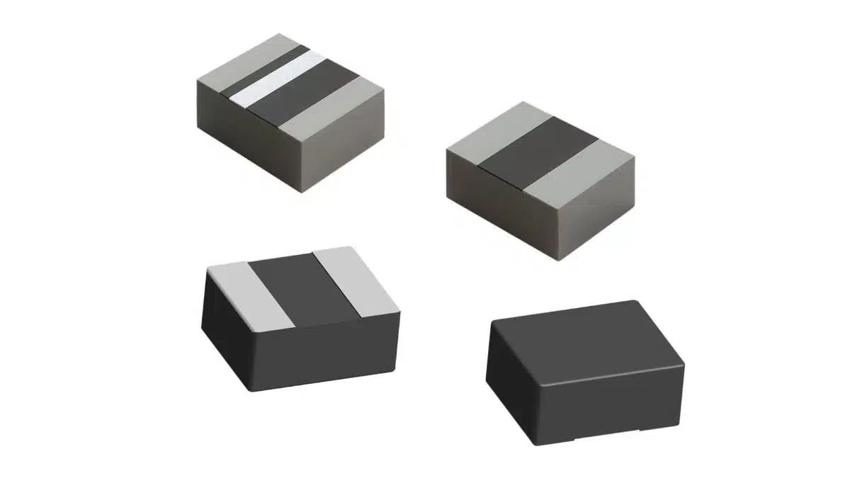
Package, footprint and terminations

A notable detail is the termination design: on IHLL commercial devices such as the IHLL-0806AZ-1Z, the terminals are plated on the bottom only.

This offers several implications:

  • Smaller land pattern: the lack of side terminations allows Vishay to recommend a more compact pad layout, which directly helps in shrinking the power stage footprint.
  • Lower profile appearance: visually and mechanically closer to a chip‑like package, which can be beneficial in dense layouts under shielding cans.
  • Solder inspection: without side fillets, optical inspection of solder joints may rely more on X‑ray or process control, compared to side‑terminated packages that show a visible fillet.

For applications where additional mechanical robustness and visible solder fillets are important (for example, harsh‑environment automotive ECUs), the related IHLP automotive‑grade series with side terminations may be a better fit, while IHLL focuses on commercial systems where board space is at a premium.

Availability and part numbers

The IHLL-0806AZ-1Z is introduced alongside the slightly larger IHLL-1210AB-1Z and two Automotive Grade IHLP devices, but it is the smallest case size in this group. According to Vishay, samples and production quantities of this family are already available through the company and its authorized distributors.

Practical procurement notes:

  • IHLL-0806AZ-1Z is the base ordering code for the 0806 commercial series; specific inductance values are defined by suffixes and must be checked in the official Vishay electrical specification table.
  • Full parametric details, including inductance table, DCR limits and current ratings, are published in the dedicated datasheet and on the Vishay product page.
  • The part is RoHS‑compliant and supplied in standard tape‑and‑reel packaging suited for high‑volume SMT assembly.

For purchasing teams, the overlap between IHLL-0806AZ-1Z and the broader IHLL/IHLP portfolio allows some second‑sourcing flexibility within Vishay’s own range, particularly when moving between 0806 and 1210 footprints or between commercial and Automotive Grade versions.

Design‑in notes for engineers

When designing in the IHLL-0806AZ-1Z, engineers should treat it as a compact, high‑current, shielded inductor optimized for modern low‑voltage regulators.

Practical selection and layout tips:

  • Start from the converter requirements: output current, switching frequency, ripple current target and transient response dictate the required inductance and current rating. Choose the IHLL-0806AZ-1Z variant whose inductance at operating current and saturation current margins meet these constraints according to the datasheet.
  • Evaluate efficiency trade‑offs: the low DCR helps, but higher inductance values within the same series typically come with higher resistance. Model conduction losses (I²R) and core losses versus switching frequency to verify junction temperature limits.
  • Check thermal environment: although the device is rated up to +125 °C ambient, nearby hot components (MOSFETs, controllers, ASICs) can raise local temperature, reducing current margins. Thermal simulation or empirical IR measurements on prototypes are recommended.
  • Pay attention to EMI: the shielded construction reduces radiated magnetic fields, but layout still matters. Keep high‑di/dt loops tight and avoid routing sensitive analog traces or high‑speed differential pairs directly under the inductor.
  • Consider mechanical constraints: the small 0806 size eases placement under shields or within stacked boards, but also means lower solder joint area compared to larger packages. Follow Vishay’s recommended land pattern and reflow profile to ensure robust joints.

From a component‑engineering standpoint, it is advisable to qualify at least two inductance values from the IHLL-0806AZ-1Z series for a given platform so that power stage variants (for example, different CPU SKUs) can share the same footprint but use different inductor values if needed. Early collaboration with purchasing to secure supply and second‑source options within the Vishay portfolio will help avoid redesigns later in the product lifecycle.vishay+1

Source

This article is based on Vishay Intertechnology’s official product press release and associated technical documentation for the IHLL-0806AZ-1Z commercial power inductor.

References

  1. Vishay press release – IHLL-0806AZ-1Z and related power inductors
  2. Vishay NPI document – Space‑saving commercial and Automotive Grade power inductors
  3. IHLL-0806AZ-1Z product page
  4. IHLL-0806AZ-1Z datasheet
  5. Circuits Assembly – Vishay releases IHLL and IHLP series power inductors

Related

Recent Posts

Vishay Introduces SMD Polymer PTC Thermistors for Fast Resettable Overcurrent Protection

30.6.2026
11

MLCCs in the Age of AI: Q2 2026 Market Tightness

30.6.2026
26

AI Hardware Demand for Passive Components Dossier

30.6.2026
25

Power Design Simulation Tools for Faster Inductor Selection and Loss Optimization

29.6.2026
15

Skeleton Supercapacitor Achieves UL‑certified 3,500 A Peak Current for AI Data Centers

26.6.2026
49

Bourns Planar Transformers for SiC and GaN Gate Driver Isolation

26.6.2026
35

100 V Hybrid Polymer Capacitor from VINA Enesol Targets 48–72 V Power Platforms

26.6.2026
103

Panasonic Releases Relays for IEC 62955 Compliant Single‑Phase EV Wallboxes

25.6.2026
23

Coilcraft Releases 0402 Ferrite-Core Wirewound Chip Inductors for RF and EMI Control

25.6.2026
27

Upcoming Events

Jul 2
17:30 - 18:30 CEST

Can Claude design a production-ready Custom Magnetic Component?

Jul 14
16:00 - 17:00 CEST

EMC Design Essentials: Mastering Varistors and Common Mode Chokes

Jul 21
16:00 - 17:00 CEST

Safety by design: X and Y Interference suppression capacitors for power line filters

View Calendar

Popular Posts

  • Boost Converter Design and Calculation

    0 shares
    Share 0 Tweet 0
  • Buck Converter Design and Calculation

    0 shares
    Share 0 Tweet 0
  • LLC Resonant Converter Design and Calculation

    0 shares
    Share 0 Tweet 0
  • Flyback Converter Design and Calculation

    0 shares
    Share 0 Tweet 0
  • MLCC and Ceramic Capacitors

    0 shares
    Share 0 Tweet 0
  • Nvidia Vera Rubin: Why One AI Rack Needs So Many More MLCC Capacitors

    0 shares
    Share 0 Tweet 0
  • Earthing Systems and IEC Classification Explained

    0 shares
    Share 0 Tweet 0
  • Dual Active Bridge (DAB) Topology

    0 shares
    Share 0 Tweet 0
  • SEPIC Converter Design and Calculation

    0 shares
    Share 0 Tweet 0
  • MLCC Case Sizes Standards Explained

    0 shares
    Share 0 Tweet 0

Newsletter Subscription


Passive Components Blog

© EPCI - Leading Passive Components Educational and Information Site

  • Home
  • Privacy Policy
  • EPCI Membership & Advertisement
  • About

No Result
View All Result
  • Home
  • Knowledge Blog
  • Dossiers
  • PCNS

© EPCI - Leading Passive Components Educational and Information Site

This website uses cookies. By continuing to use this website you are giving consent to cookies being used. Visit our Privacy and Cookie Policy.
Go to mobile version